
- Prisma & Filtros
- Partes ópticas personalizadas
- Iluminación & Iluminación
- Medicina & Endoscopia
- Aplicaciones ópticas
- Óptica automotriz
- Imagen & Visión
- Capacidades ópticas
- Productos & Aplicaciones
- Recurso
- Ópticas de vidrio personalizadas
- Moldes ópticos
- Recubrimiento OPático
- Moldeo óptico
- Herramientas ópticas
- Videos de Herramientas
- Electrónica de consumo
- Visión industrial
- Lentes Asféricas
- Lentes Esféricas
Diffraction Grating RFQ: Reference the Grooves to a Mounting Edge
Indagación- Descripción
A drawing can specify the right groove density and still leave the grating ambiguous in its mount. Groove orientation determines the plane in which orders separate, so show how the ruled surface is oriented relative to a mechanical feature the assembler can actually identify. Do not assume that a rectangular blank has its grooves parallel to the long edge.
Choose the viewing direction and datum
Draw the active face as seen from the incident side and indicate one edge, flat or keyed feature as the reference. Draw the groove lines and mark the permitted angle between the lines and that reference. Show which face is active and, where a blazed reflection grating is directional, show the installed orientation rather than relying on a line with no arrow. If an identifying mark is needed, reserve space outside the clear aperture and make sure the mount does not cover it.
Describe the order the instrument uses
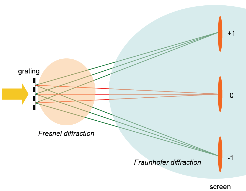
Identify the design wavelength or band, the order and the intended incident and diffracted directions in a labeled section. State the angle sign convention rather than assuming positive order means the same thing on every drawing. Ask for efficiency data in the order the instrument collects and at the planned geometry and polarization where relevant; an angle check and an efficiency check answer different questions.
Agree how the delivered orientation will be checked
Define whether acceptance is a groove-to-edge check on the loose optic or a beam placement check on a mounted assembly. For the latter, give the receiver plane and where the accepted spot may land. Share the section and mounting drawing with the glass optics project team when reviewing the mechanical interface; confirm grating scope separately. For the relationship between grating geometry, orders and efficiency, consult Edmund Optics’ diffraction grating guide.
Recurso, Blogs
ENVIAR CONSULTA
Productos relacionados
© Silveroptics 2026. Todos los derechos reservados
Funciona con Silveroptics
Servicio
