
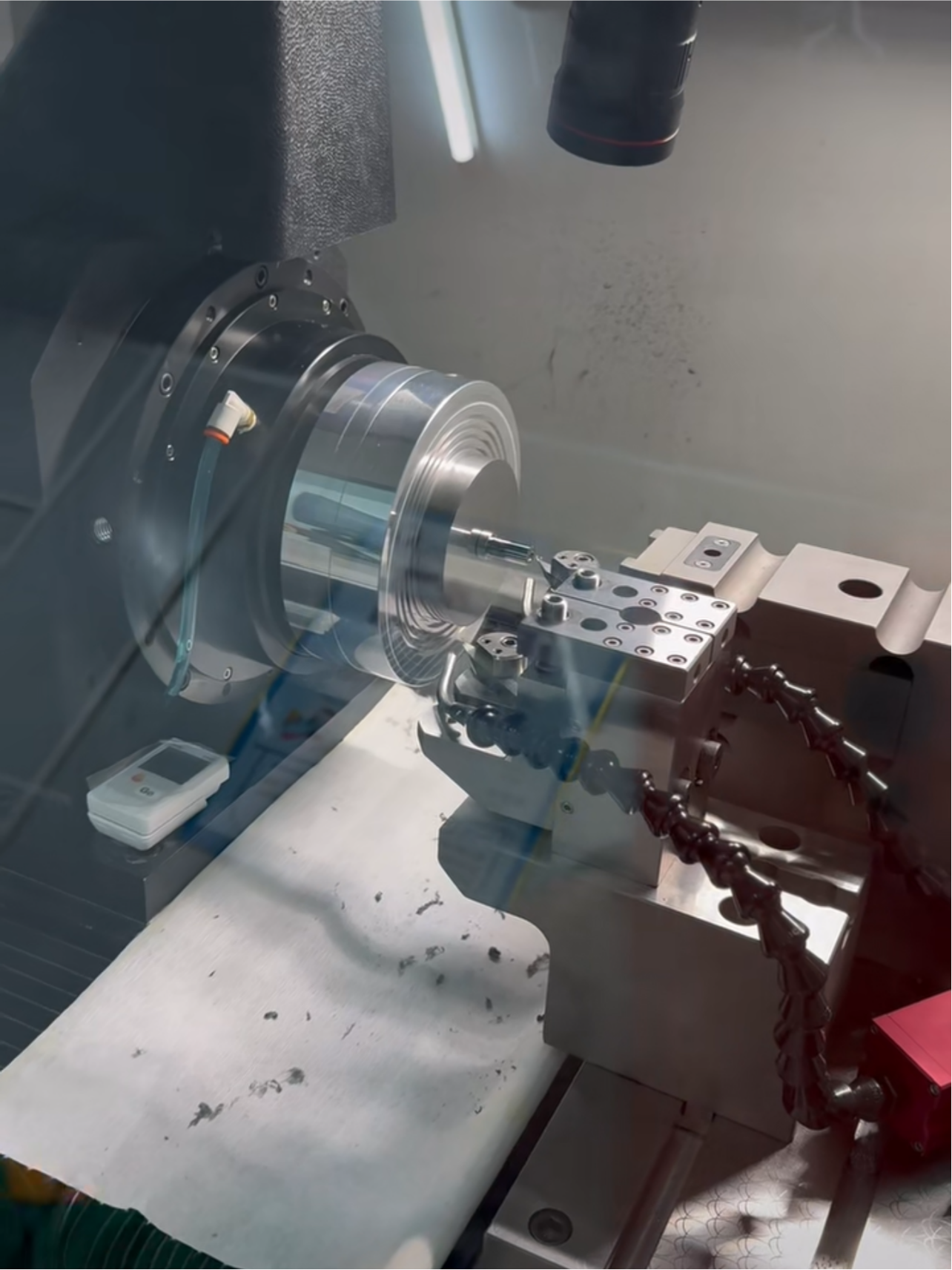
Case Study · Process reference
Diamond-Turned Optical Inserts: Planning Surface Acceptance
A process-led study connects optical geometry, cutting-surface identification, texture reporting and mounting datums in a practical mold-insert review.
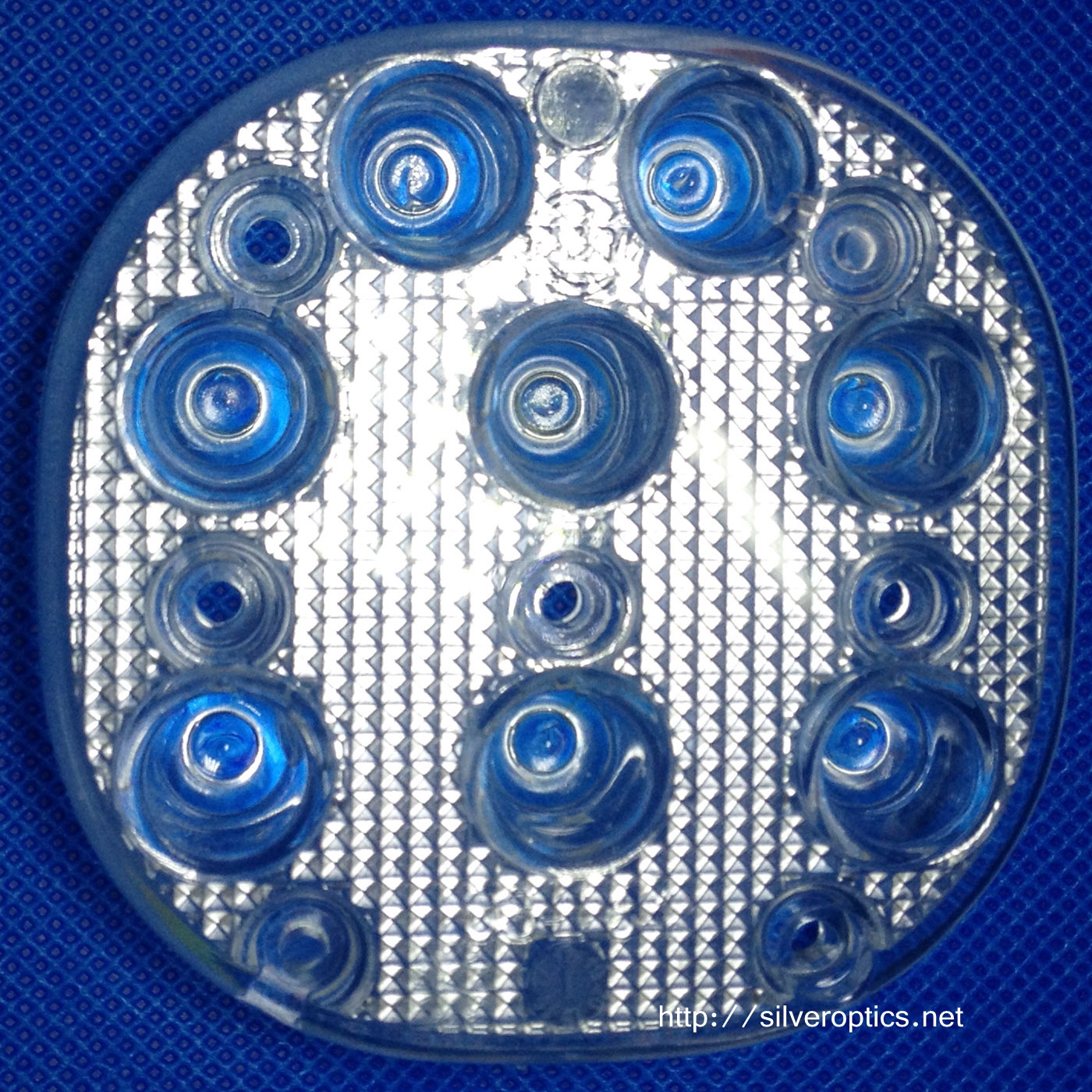
A circular array creates an interesting tooling question: how should a team review many repeated optical features as both individual surfaces and one molded component? This technical study uses a PMMA array disc shown in the Silver Optics presentation to develop a practical review sequence.
Based on mold and sample photographs in the company presentation; the inspection steps below are engineering recommendations, not reported test results.
The presentation groups a transparent circular array sample with photographs of tooling showing a similar repeated-feature arrangement. The slide identifies PMMA and an export mold. These images provide a useful basis for discussing array manufacture, although they do not establish a traceable match between a particular mold revision and sample batch.
The defining visual feature is repetition across a common disc. Reviewing that geometry calls for two levels of attention: the shape and condition of each element, and the position of those elements within the complete component.
A useful first deliverable is an annotated plan view. Give every element a stable identifier, select an orientation reference, and retain that convention in the CAD model, tool review and inspection report. Numbering must remain understandable when the mold and part are viewed from opposite directions.
Weiter, distinguish the optical working areas from surrounding support geometry. Review the proposed parting line, gate contact, ejection contact and handling locations against that map. Any keep-out area should be drawn explicitly. A note such as “optical surface” becomes more useful when its boundary and associated requirements are clear.
For the tool review, consider how individual features will be manufactured, accessed for inspection and maintained. The photographs do not establish whether the array uses separate inserts or one continuous insert, so that construction choice belongs in the engineering discussion.
A recommended sequence for an array of this type is:
Use the same feature map when recording visible marks or incomplete detail. That makes a report actionable: a reviewer can locate the observation on the part and then find the corresponding area in the tool model.
Supply the full array model, an element-index drawing, the specified PMMA grade and the optical-area boundaries. Include the mounting reference, permitted gate and ejection regions, expected order quantities and required inspection coverage. If nominally repeated elements intentionally have different prescriptions, identify those differences before tooling review.
For export tooling, also identify the receiving machine and the documentation expected at handover. Those requirements are separate from the visual appearance of the array sample.
This portfolio example is most useful as a concrete starting point for discussing repeated-feature tooling. Explore Silver Optics’ optical mold structures und optischem Formen, oder send the array model and inspection priorities for a project discussion.
A process-led study connects optical geometry, cutting-surface identification, texture reporting and mounting datums in a practical mold-insert review.
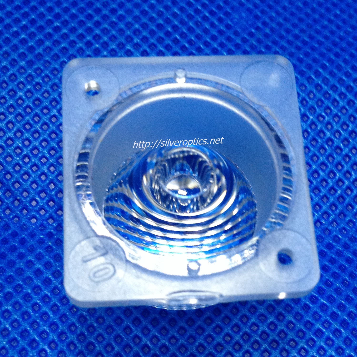
Concentric-ring PC samples and a mold photograph provide the basis for an inspection strategy that records radial position, direction and feature definition.
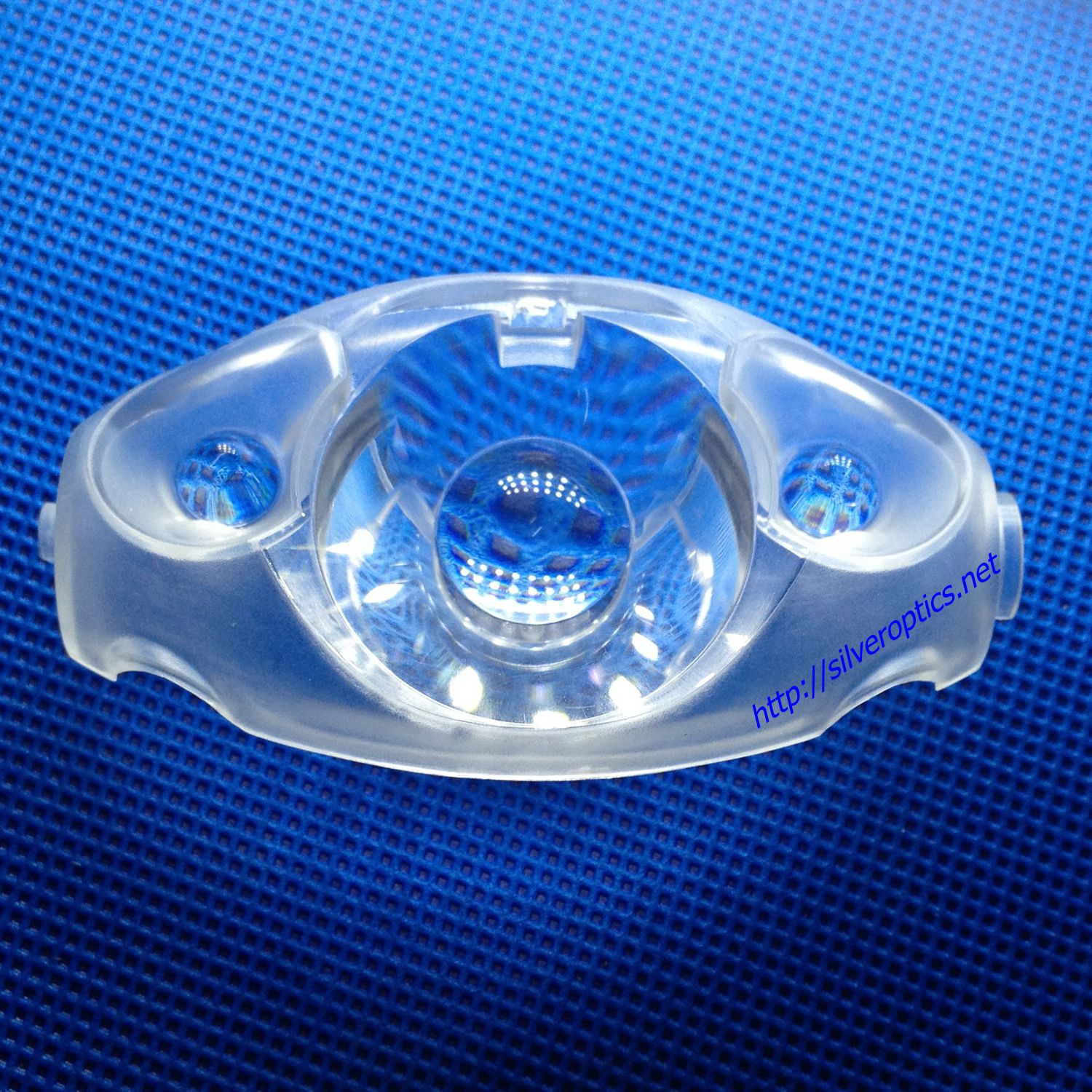
A curved PMMA sample, cavity view and full mold photograph anchor a technical study of surface definition, protected regions, measurement access and handling.
Share your optical drawings, material requirements and inspection priorities. Discuss tooling, molding and the next steps with Silver Optics.
