
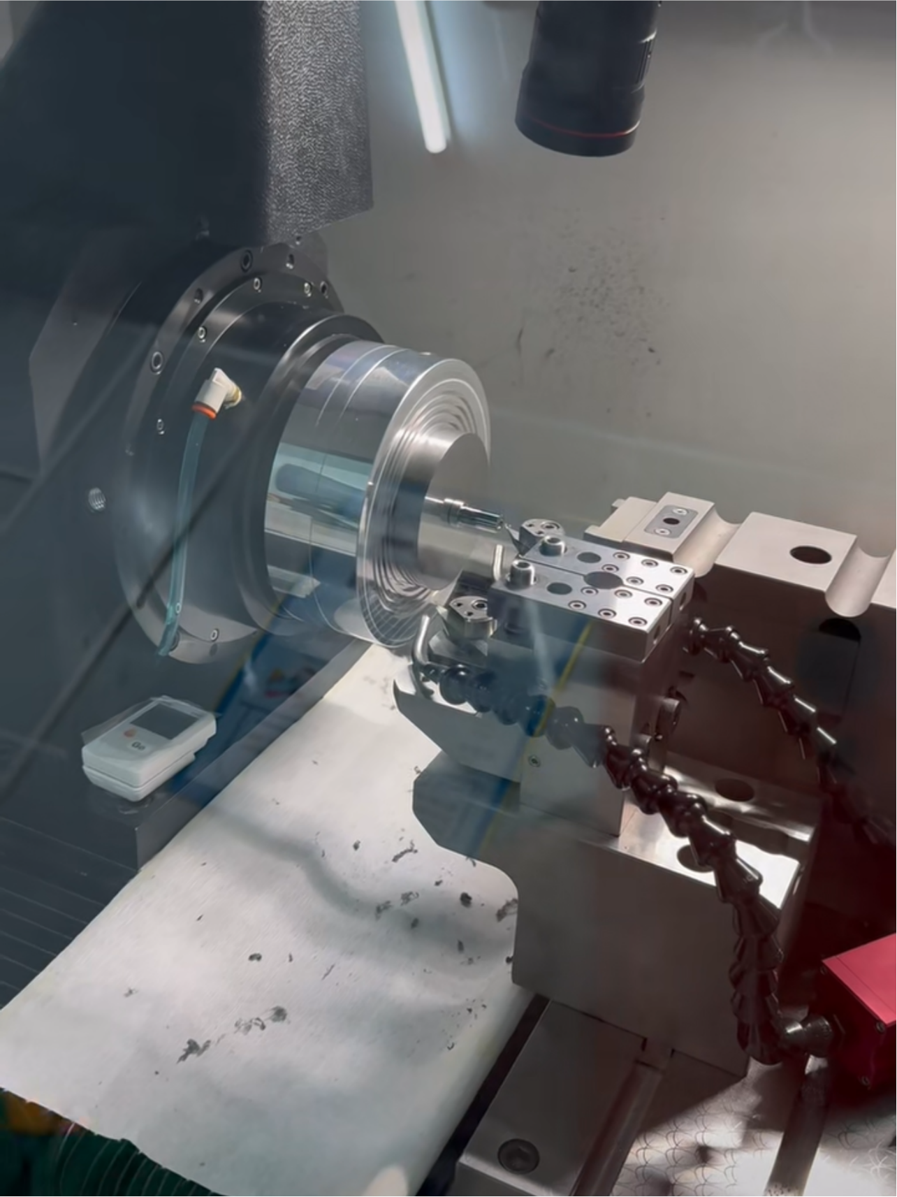
Case Study · Process reference
Diamond-Turned Optical Inserts: Planning Surface Acceptance
A process-led study connects optical geometry, cutting-surface identification, texture reporting and mounting datums in a practical mold-insert review.
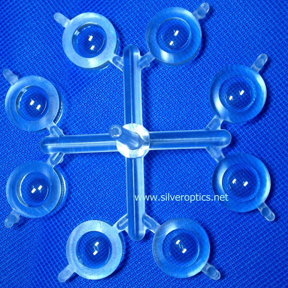
A multi-cavity mold produces a group of parts that should remain identifiable throughout evaluation. The PC example in the Silver Optics presentation offers a concrete starting point: three circular cavity positions and a transparent runner-connected sample. The technical focus here is preserving that relationship as samples move from molding to inspection.
This study draws on mold and sample photographs in the company presentation. The proposed checks are engineering recommendations rather than documented trial or customer acceptance results.
The source identifies PC and illustrates a three-position circular layout. Its photographs support a discussion of cavity mapping and runner-to-part relationships. They do not specify the resin grade, component thickness, optical prescription or intended application.
Those missing details matter when selecting a process and test method. The visible number of cavities alone cannot establish output rate, balanced filling or equivalent optical performance across the three positions.
Begin with an orientation-controlled photograph or drawing of the mold layout. Assign cavity identifiers using a fixed viewing direction. Make the relationship between that drawing and the runner-connected sample explicit, including any reversal between the mold view and the molded assembly.
For an initial evaluation, retain a record of each complete shot before the parts are separated. After separation, place the three samples in individually identified locations and carry the shot reference into every inspection record. This allows a reviewer to compare the three cavities within one shot and one cavity across successive shots.
Keep identification outside the specified optical working area. The labeling method itself should be reviewed for compatibility with the part and its subsequent use.
The runner-connected sample makes the feed arrangement visible, but a photograph is insufficient to judge its balance. Request the actual runner and gate dimensions, relevant part sections and the proposed processing assumptions before evaluating the layout.
Covestro’s gate-design guidance explains that gate position affects the filling pattern and that gate sizing depends on several material and part variables. Applied here, the practical recommendation is to review each cavity’s feed path with the specified PC grade, rather than assigning processing settings from the photograph.
A recommended sample evaluation would cover four stages:
Where optical function is part of the specification, use the same fixture, orientation and test conditions for all three positions. The acceptance limits and sampling quantity must come from the project requirements.
Send the part model, material grade, optical-area definition, mounting references and permitted gate vestige. Include the required production quantity, proposed cavity count and how samples must be identified in the inspection package. Ask for the runner concept and cavity-identification method to be included in the tooling review.
See Silver Optics’ mold structure options und quality information, oder discuss a cavity-specific inspection plan.
A process-led study connects optical geometry, cutting-surface identification, texture reporting and mounting datums in a practical mold-insert review.
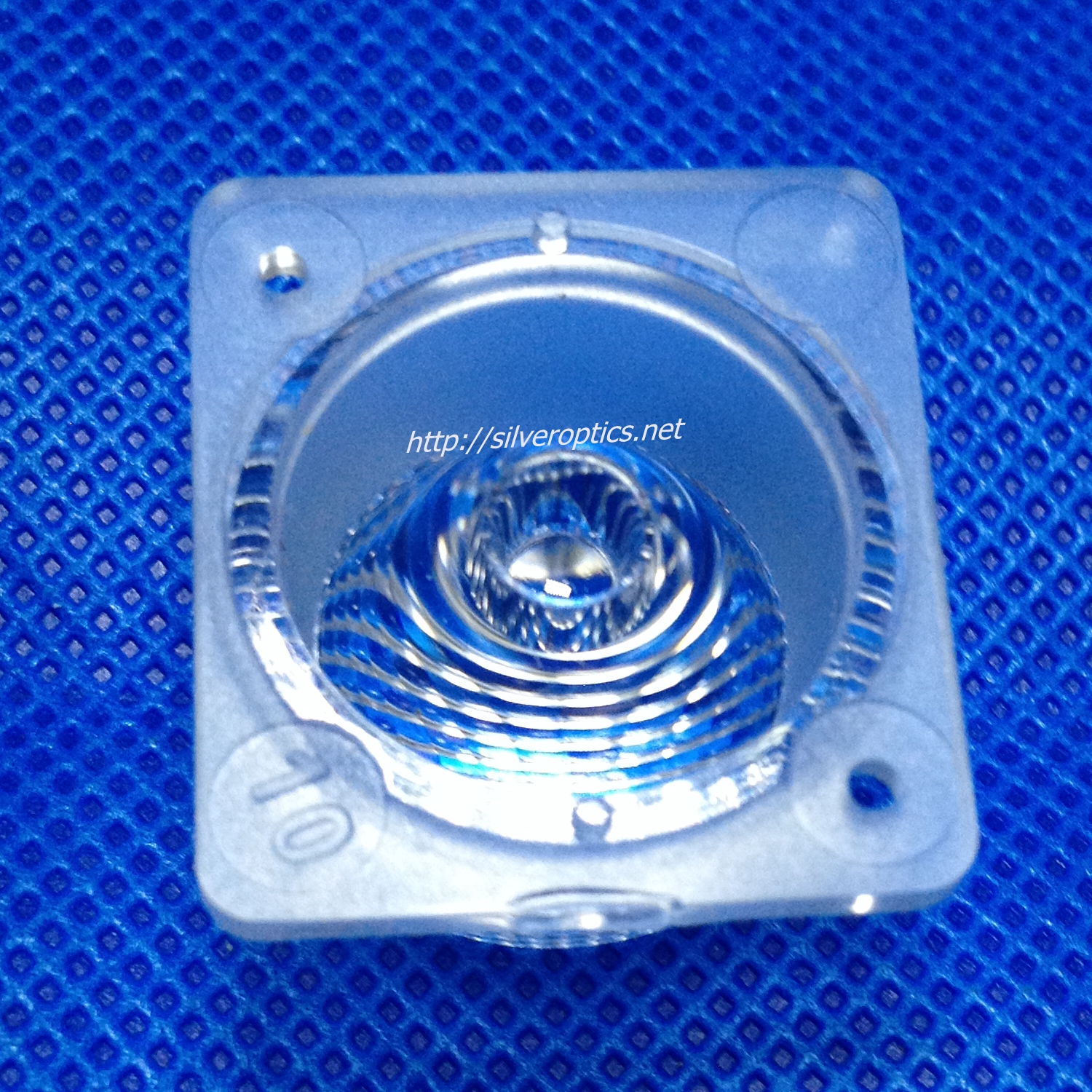
Concentric-ring PC samples and a mold photograph provide the basis for an inspection strategy that records radial position, direction and feature definition.
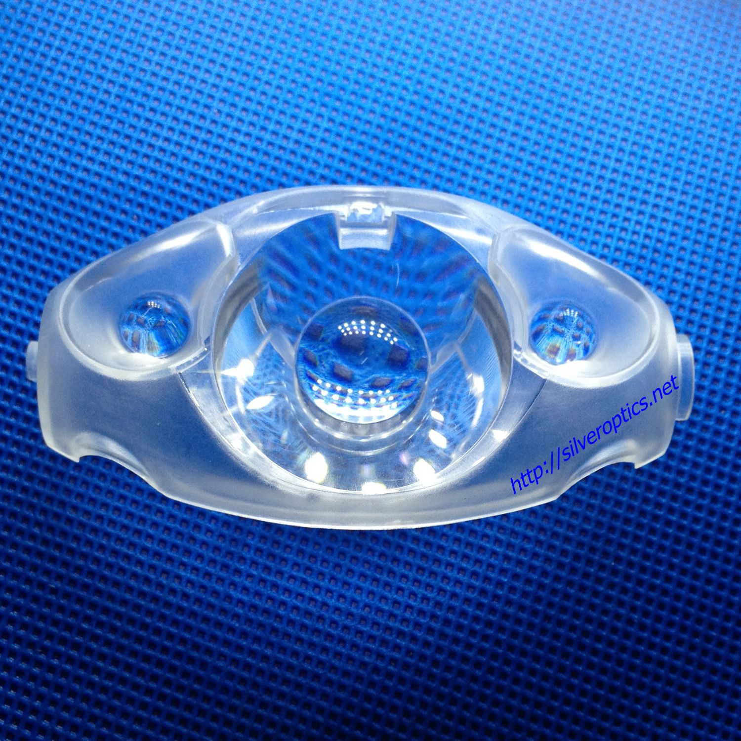
A curved PMMA sample, cavity view and full mold photograph anchor a technical study of surface definition, protected regions, measurement access and handling.
Share your optical drawings, material requirements and inspection priorities. Discuss tooling, molding and the next steps with Silver Optics.
