
Case Study · Reference image
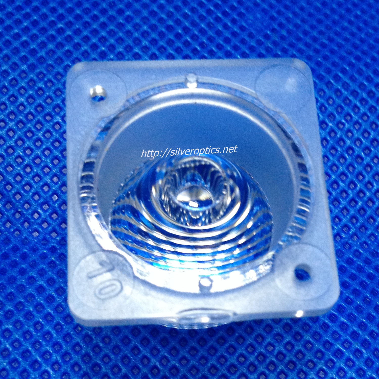
PC Concentric Features: Planning a Radial Inspection Map
Concentric-ring PC samples and a mold photograph provide the basis for an inspection strategy that records radial position, direction and feature definition.
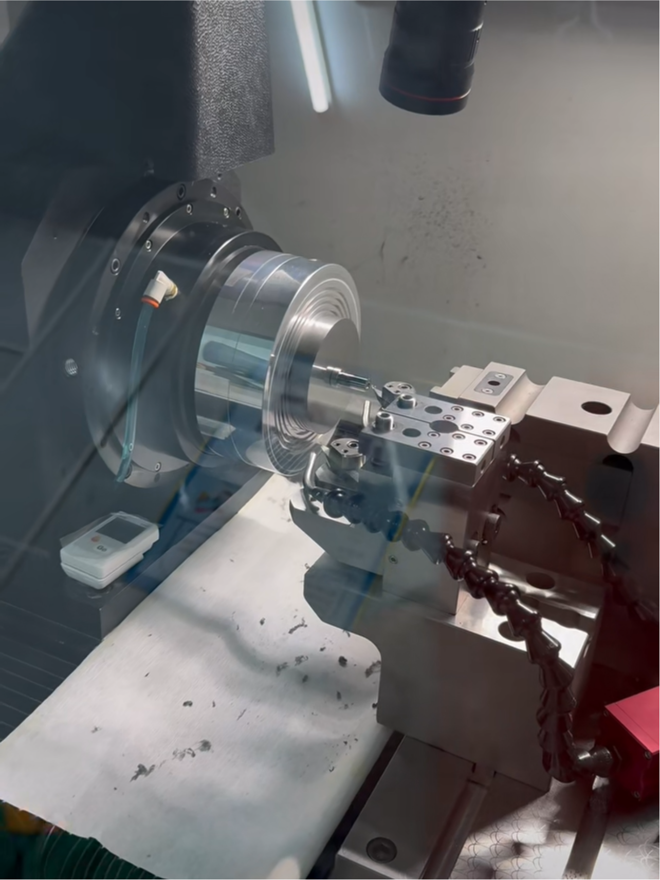
An optical mold insert needs more than a reflective appearance. Its working surface must have a defined shape, a controlled texture and a known relationship to the mounting features. This technical study uses the diamond-turning process shown in Silver Optics’ tooling materials to organize those requirements into a practical review package.
This is a process-planning study, not a reported customer acceptance test. The steps below describe a proposed inspection and handover method; project-specific results and numerical performance are not claimed.
A photograph can document the setup and visible condition, but it cannot establish surface-form error or roughness. For an insert that will reproduce an optical surface, the review should therefore separate the nominal profile, local texture and mounting relationship instead of accepting one appearance photograph as evidence for all three.
Silver Optics’ diamond-turning service overview identifies optical geometry, surface texture and mechanical datums as linked requirements. The practical task is to convert that description into checks that another engineer can interpret and repeat.
Start with a controlled drawing revision and the surface definition used for manufacturing. Identify the clear aperture, optical axis, seating face and locating features. Show where the functional surface ends and which adjacent lands, edges or transitions must remain protected.
For a replacement insert, include the interface to the surrounding mold. A surface report without the relevant seating and location references leaves the installation requirement unresolved. The proposed review package should include a drawing view that connects the optical region with those mechanical references.
Record the substrate and any coating as separate items. Ask for the specified material condition and available finishing allowance rather than inferring them from a shiny photograph. The cutting route, handling method and inspection sequence should be agreed against that documented surface system.
This study does not identify the photographed workpiece’s alloy or coating. Those details belong in the project record before process capability or acceptance limits are discussed.
The form report should identify the nominal surface, measured aperture, orientation and any excluded region. A texture report should identify the measured locations, measurement settings and reported parameters. Keep the settings with the result so a later comparison is meaningful.
Precitech’s camera-lens mold application note reports surface finish and observations of tool marks under defined test conditions. It is a useful example of why a finish number needs a measurement context. Its machine settings and performance results are not Silver Optics specifications or results for the pictured setup.
Add location-marked images of the center region, aperture boundary and any visible area requiring review. Record the viewing side and illumination so observations can be compared. Protect the functional surface during handling and note the insert identity on its packaging or accompanying record.
If a correction is proposed, identify the affected region and the checks to repeat afterwards. Avoid treating an additional finishing step as automatically beneficial without reviewing its effect on the approved geometry.
Prepare the drawing and model revision, substrate and coating details, aperture and datum map, proposed form and texture reports, and location-marked condition photographs. State the intended molding application and the information that still needs confirmation.
For the next step, review aspheric insert tooling o send your insert requirements to Silver Optics. A focused technical review can then establish the manufacturing and inspection scope before quotation.
Case Study · Reference image
Concentric-ring PC samples and a mold photograph provide the basis for an inspection strategy that records radial position, direction and feature definition.
Case Study · Reference image
A curved PMMA sample, cavity view and full mold photograph anchor a technical study of surface definition, protected regions, measurement access and handling.
Case Study · Reference image
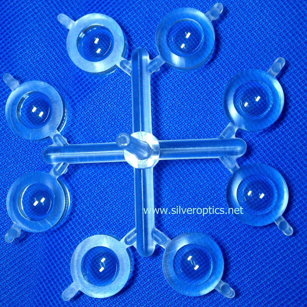
A three-cavity PC portfolio layout provides a concrete basis for preserving cavity identity, comparing complete shots and inspecting samples before and after separation.
Share your optical drawings, material requirements and inspection priorities. Discuss tooling, molding and the next steps with Silver Optics.
