PC Concentric Features: Planning a Radial Inspection Map
October 6, 2026
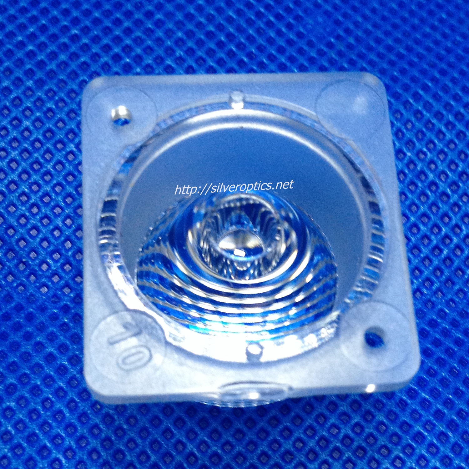
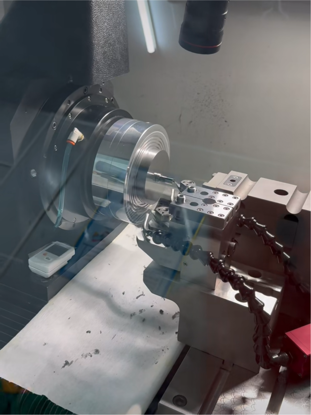
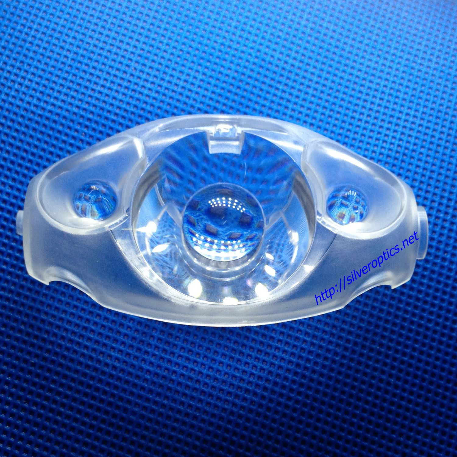
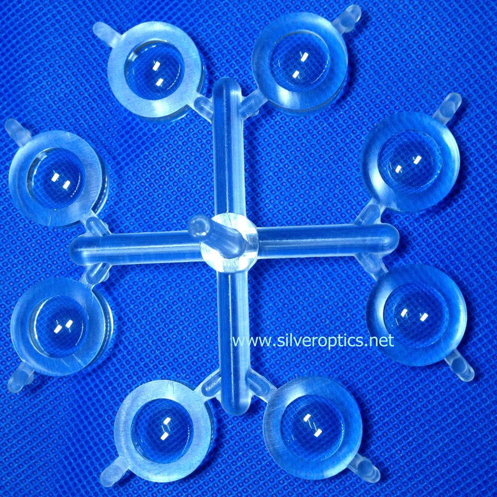
Optical component reference image; not the PC portfolio sample discussed in this study.
Concentric features need an inspection plan that preserves where an observation was made. A result described only as “surface profile” can leave a toolmaker unsure which ring, direction or region needs attention. This technical study uses the PC concentric-ring samples and mold photograph in the Silver Optics presentation to outline a more specific review approach.
The source is the company presentation’s portfolio photography. The inspection plan developed here is recommended engineering practice for this geometry, not a reported production test.
Begin with the visible geometry
The sample image presents four circular areas with visible concentric features, accompanied by a mold photograph. The slide identifies PC. This supports a study of repeated radial geometry, but does not supply feature dimensions, an optical prescription or a measurement report.
Concentric appearance alone is insufficient to classify the part as a Fresnel lens. The working definition must come from the drawing or design model. Likewise, no claim about microscopic feature size or replication accuracy can be made from the photograph.
Turn the rings into a measurement map
Begin with the specified center and orientation reference. Define how ring positions are identified and how angular directions are recorded. Use the same convention in the model, tool review and sample report so each result can be traced to a physical location.
Describe the intended cross-section before choosing a measurement. Depending on the actual design, relevant characteristics may include radial spacing, height, slope or the shape of a transition. Only include characteristics that the supplied geometry and functional requirement support.
Keep the designed concentric features distinguishable from any unwanted surface texture. The intended geometry, permissible variation and inspection filtering should be agreed together. A measurement plan should explain what is being evaluated and what processing has been applied to the data.
Review the tool around the feature definition
For the tooling discussion, examine how the defined features will be formed and inspected. Review release direction, any proposed draft and access for manufacturing or maintenance against the optical geometry. A change to a ring transition should be assessed against the design before it becomes a tooling convenience.
Mark regions proposed for gating, ejection and handling. If they overlap a functional region, resolve that conflict in the model review. Also establish which tool areas would need to be remeasured after finishing or maintenance; the source photographs do not document those operations.
Build coverage in both radius and direction
A recommended evaluation sequence is:
Record the sample and drawing revision, locate the specified center, and confirm the measurement orientation.
Select radial sections at documented angular directions. Include the relevant inner, intermediate and outer regions instead of reporting an unspecified representative trace.
Compare measured features with the nominal cross-section at the corresponding locations. Record incomplete coverage and inaccessible transitions explicitly.
Repeat selected locations to check the stability of the setup before interpreting differences between samples or regions.
Add the specified functional optical test, with its aperture and illumination conditions, when the optical design requires one.
The measuring method must be suitable for the feature geometry and surface. ZYGO’s optical profiler overviewidentifies vertical range, precision and application requirements among the factors in selecting a system. Instrument selection should therefore follow the actual geometry rather than the photograph’s apparent level of detail.
Supply the data behind the pattern
For an RFQ, provide the model, specified PC grade, radial feature definition, center reference and allowed nonfunctional regions. Include the desired measurement coverage and any optical test requirement.
A process-led study connects optical geometry, cutting-surface identification, texture reporting and mounting datums in a practical mold-insert review.
A curved PMMA sample, cavity view and full mold photograph anchor a technical study of surface definition, protected regions, measurement access and handling.
A three-cavity PC portfolio layout provides a concrete basis for preserving cavity identity, comparing complete shots and inspecting samples before and after separation.
Silver Optics·
Get Started with Your Optical Component and Mold Project
Share your optical drawings, material requirements and inspection priorities. Discuss tooling, molding and the next steps with Silver Optics.