HogarEstudios de CasoArrays, Grids and Curves: A Comparative Optical Inspection Study
Arrays, Grids and Curves: A Comparative Optical Inspection Study
October 6, 2026
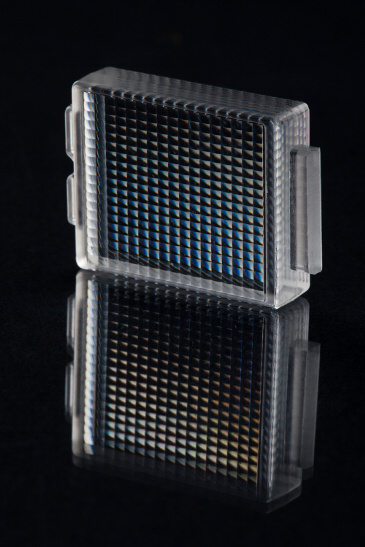
Reference image: a transparent grid-pattern optical component. This illustrates the geometry family, not the square blocks or other samples discussed below.
A circular array, a square grid and a curved component can all appear in an optical-plastic sample collection, yet each needs a different way to locate and describe its important features. The collection in the Silver Optics presentation provides a useful basis for comparing those inspection choices.
This is a comparative study of portfolio photographs, not a separate customer project. The inspection approaches below are engineering recommendations rather than reported test results.
Three geometries in one sample collection
The source photographs show optical-plastic samples with disc-array, square-grid and curved forms. Their presence together illustrates a range of geometry. It does not establish a shared customer, common resin grade, production batch or inspection history.
The practical question is how an inspection package should change when the shape changes. A reusable reporting structure can retain the same sample-identification fields while giving each geometry its own measurement map.
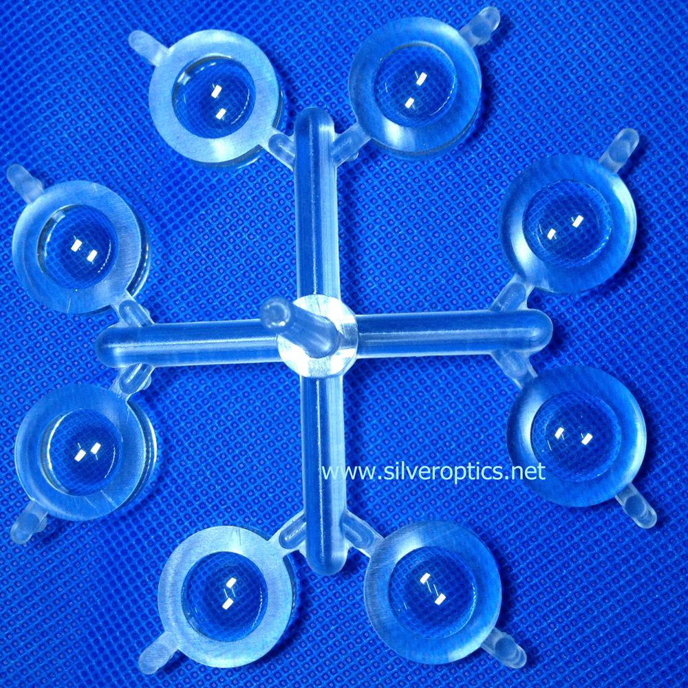
Disc arrays: preserve the identity of each element
For a circular array, assign identifiers to the individual elements and define the orientation of the complete component. The inspection report should show where each measured element sits within the disc and which nominal geometry applies to it.
A proposed sampling map should include positions from different parts of the array. The drawing and risk review determine the final coverage. Where repeated elements deliberately differ, preserve those differences in the reference data rather than comparing every feature with one assumed master shape.
The useful output is an element-level record tied to a complete-part view. That supports a tooling discussion about a specific location without losing the arrangement of the overall array.
Square grids: make row and column references unambiguous
For a square-grid sample, a row-and-column convention offers a practical addressing system. Define the origin, the direction of increasing indices and the viewed side. Add an orientation reference that remains clear when the sample is turned over.
Review the specified cell geometry and the relationship between cells separately. Depending on the drawing, inspection may need to address individual feature shape, spacing or the condition of boundary regions. Record the chosen locations so edge, corner and interior observations can be distinguished.
If the grid is inspected in several fields of view, specify how those fields are registered. A combined image should retain enough location information for a reviewer to trace an observation back to the correct cell.
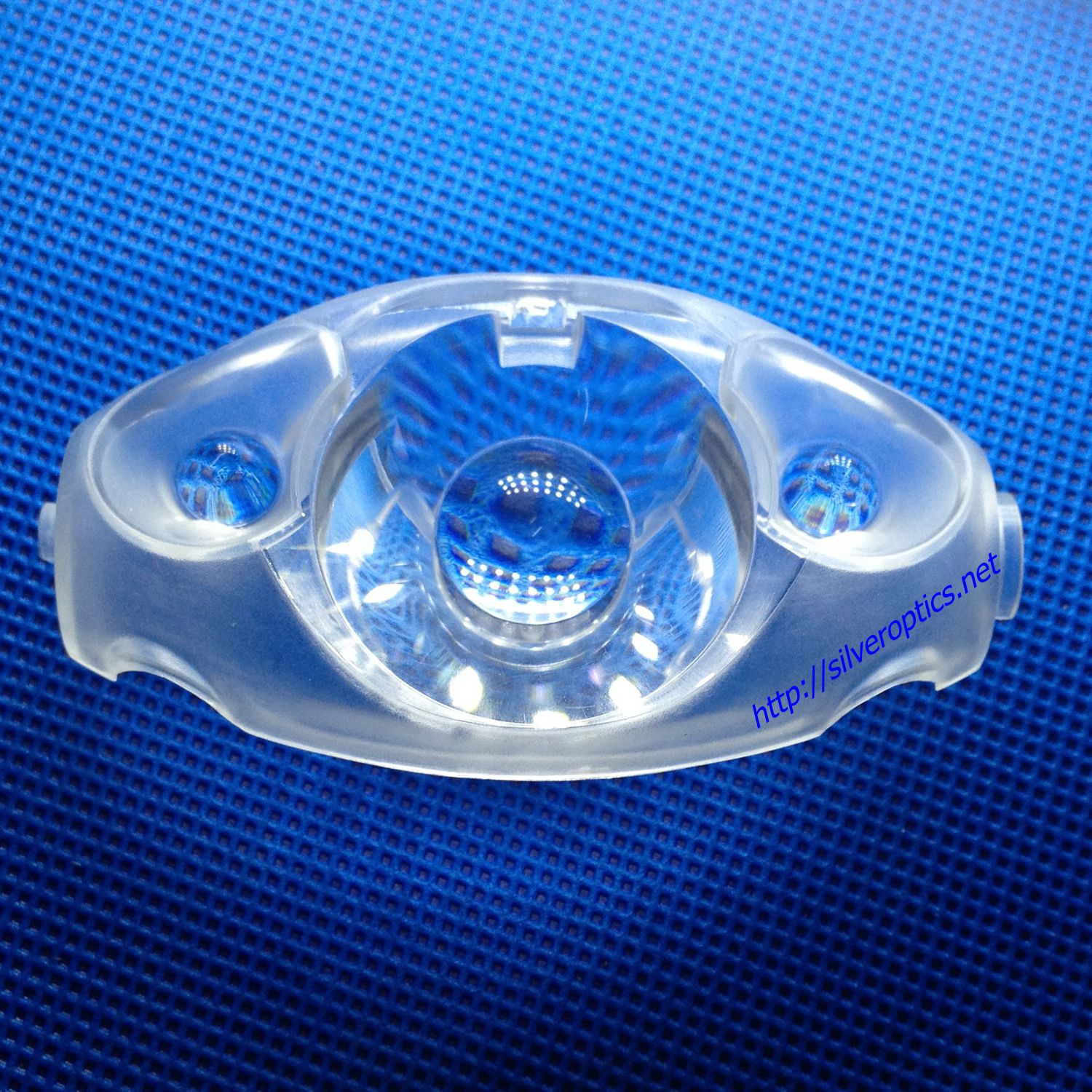
Curved components: define the measured surface region
For a curved component, start with the nominal surface and its relationship to the mounting reference. Mark the working aperture and the area the selected measurement method will cover.
The report should state how the sample was supported and oriented, which regions were measured, and whether any data were excluded. Keep surface-form measurements and visible-condition photographs identifiable as separate records. Add the functional optical test when its configuration and acceptance requirements are defined.
This approach makes the reported surface result interpretable within the component’s intended assembly.
Use one evidence structure with geometry-specific maps
Across all three geometries, retain the same basic chain: part revision, sample identity, material identification where available, measurement setup and result location. If samples come from several cavities or molding runs, carry those identifiers through the package as well.
For technical context, ZEISS’s plastic-part inspection guidancedescribes drawing- or CAD-based measurement planning and cavity comparison. The application here is to define the reference geometry and traceability before comparing results. The final sampling quantity and acceptance criteria remain project-specific.
Prepare a geometry-led RFQ
Send the complete model, intended function, specified material and critical regions. Include an annotated feature map or aperture definition and explain which inspection records are needed for review.
A process-led study connects optical geometry, cutting-surface identification, texture reporting and mounting datums in a practical mold-insert review.
A curved PMMA sample, cavity view and full mold photograph anchor a technical study of surface definition, protected regions, measurement access and handling.
A three-cavity PC portfolio layout provides a concrete basis for preserving cavity identity, comparing complete shots and inspecting samples before and after separation.
Silver Optics·
Get Started with Your Optical Component and Mold Project
Share your optical drawings, material requirements and inspection priorities. Discuss tooling, molding and the next steps with Silver Optics.