Ensuring the quality of plastic optical molds is a systematic process that runs through material selection, design optimization, precision machining, surface treatment, assembly debugging, and post-production maintenance. Below is a detailed, professional breakdown of the core measures:
The base material of the mold directly determines its hardness, wear resistance, and dimensional stability—critical factors for optical component precision.
- Select high-performance mold steel: Prioritize corrosion-resistant, high-hardness steels such as SUS440C, SKD11, H13, or powder metallurgy steel (e.g., ASP23). These materials can maintain stable dimensions after repeated heating and cooling cycles, avoiding cavity deformation that affects optical surface accuracy.
- Standardize heat treatment processes: Conduct quenching and tempering to achieve a hardness of 58–62 HRC for the mold core and cavity. Perform stress relief annealing before machining to eliminate internal stress caused by forging or cutting, preventing long-term deformation of the mold during use.
- Opt for corrosion-resistant coatings for special scenarios: For molds used to process corrosive optical plastics (e.g., PC with additives), apply TiN or CrN coatings to enhance surface corrosion resistance and reduce friction.
Optical mold design must focus on minimizing product deformation and ensuring uniform melt filling, while complying with optical component tolerance requirements.
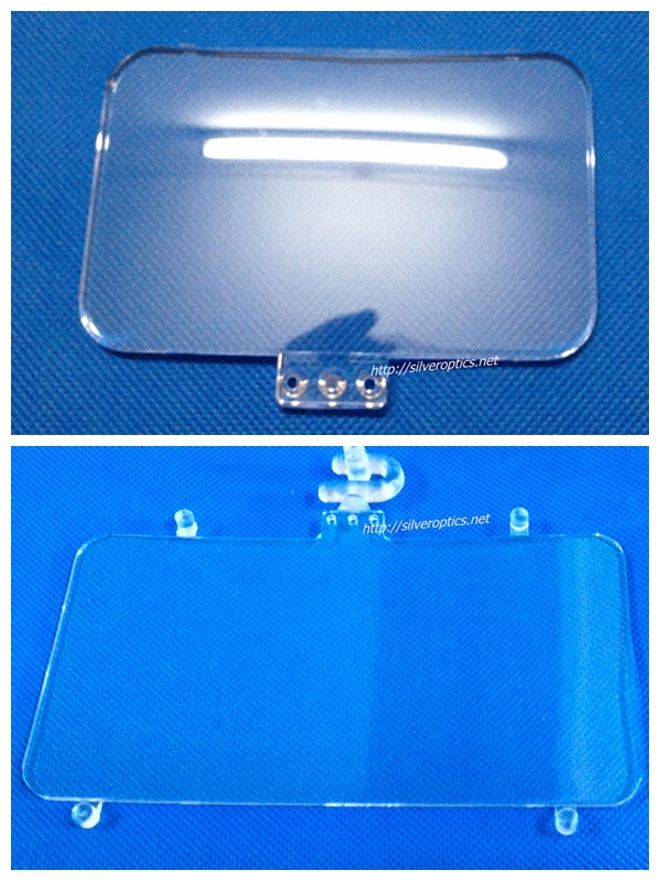
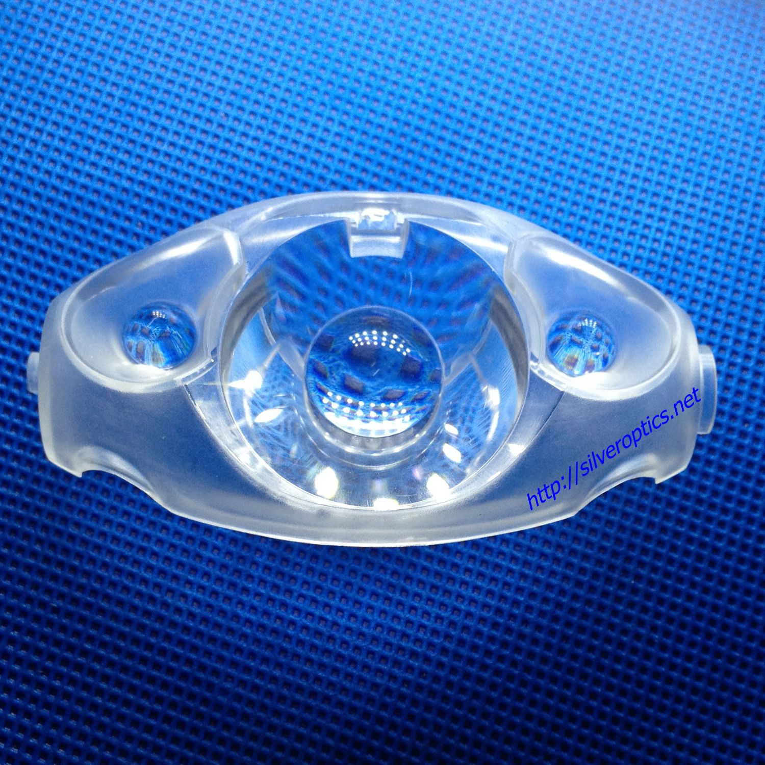
- Optimize cavity and core surface design: The cavity surface must be designed with ultra-smooth finishes and strict geometric accuracy (e.g., spherical or aspherical profiles with tolerance ≤ ±1 μm). Avoid sharp corners or sudden thickness changes to prevent stress concentration in the molded optical parts.
- Adopt advanced gating systems: Use hot runner systems instead of cold runners to reduce material waste and ensure uniform temperature distribution of the melt. For micro-optical components, employ pinpoint gates or sequential valve gates to control filling speed and avoid flow marks or weld lines.
- Integrate cooling system simulation: Use CAE software (e.g., Moldflow, Simcenter 3D) to simulate the cooling process. Design a uniform cooling channel layout (e.g., conformal cooling channels) to minimize temperature differences across the cavity surface, reducing product warpage and internal stress.
- Consider demolding feasibility: Design a soft ejection mechanism (e.g., ejector pins with polyurethane pads or vacuum suction devices) to prevent scratches on the optical surface during demolding.
This is the most critical step in ensuring mold quality, as even micron-level errors can lead to optical performance degradation of the final product.
- Use ultra-precision machining equipment:
- For cavity rough machining: Use high-speed CNC milling machines with positioning accuracy ≤ ±0.001 mm.
- For precision shaping: Adopt CNC ultra-precision lathes or slow-feeding wire EDM machines to process complex surfaces (e.g., aspherical lenses) with sub-micron precision.
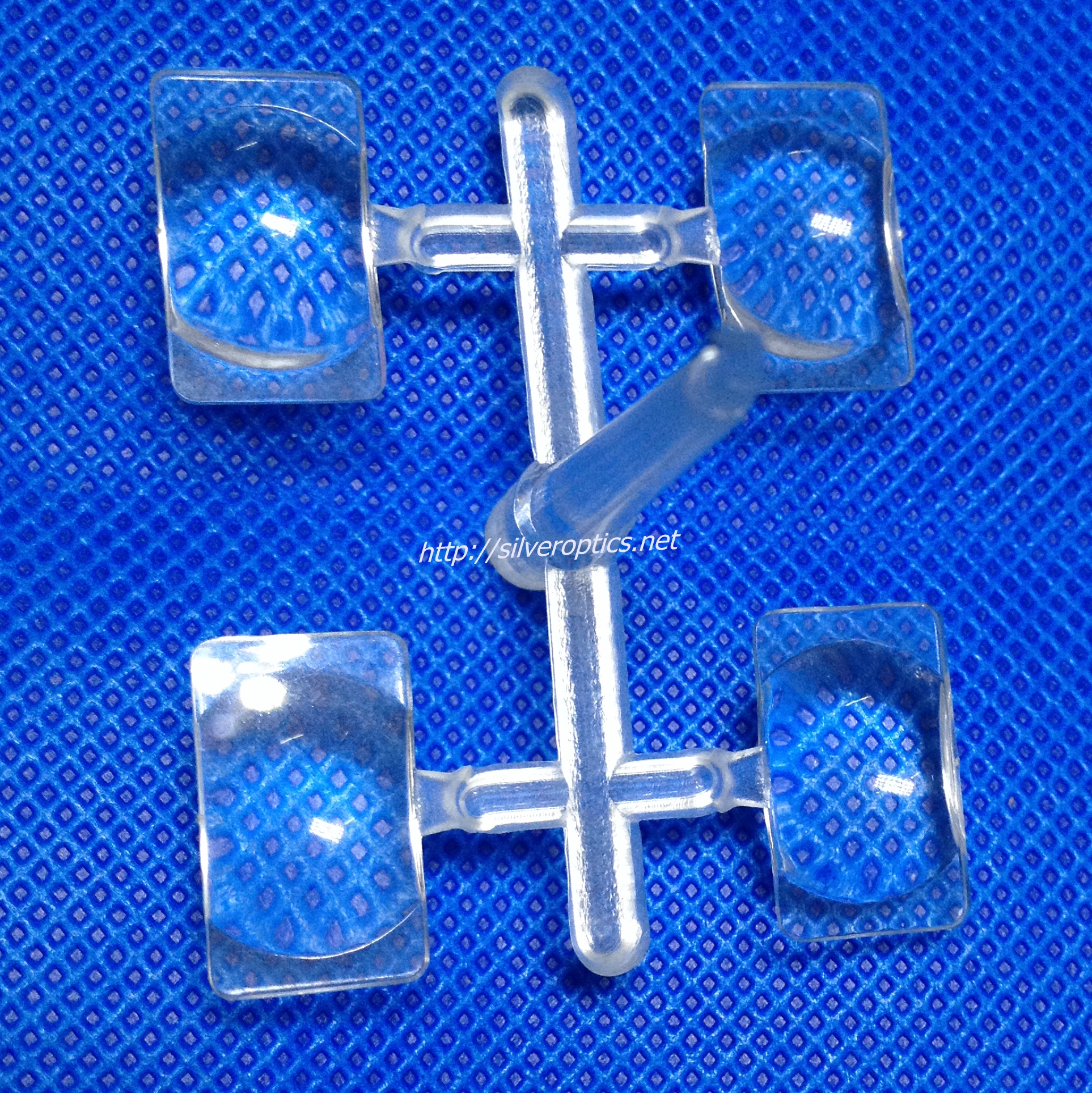
- For micro-structured optical molds: Use laser micromachining or ion beam etching to fabricate micro-nano structures (e.g., light guide plate dots).
- Implement multi-stage surface polishing:
- Conduct mechanical polishing (using diamond pastes of graded particle sizes: 3 μm → 1 μm → 0.25 μm) to achieve a preliminary smooth surface.
- Perform chemical mechanical polishing (CMP) to eliminate micro-scratches and residual stress, achieving a surface roughness of Ra ≤ 0.001 μm—a key requirement for high-transmittance optical components.
- Use laser interferometers to inspect surface flatness and profile accuracy after polishing, ensuring compliance with design specifications.
Precise assembly and debugging prevent errors caused by component misalignment, which directly impacts mold performance.
- Standardize assembly procedures: Use precision measuring tools (e.g., coordinate measuring machines, CMM) to calibrate the position of the core, cavity, guide pillars, and guide sleeves, ensuring coaxiality and parallelism within ±0.002 mm.
- Conduct trial molding and parameter optimization: Install the mold on a high-precision injection molding machine and perform trial runs with optical-grade plastics (e.g., PMMA, PC, COP). Adjust process parameters (injection pressure, temperature, cooling time) to eliminate defects such as burrs, bubbles, or sink marks.
- Inspect trial products for optical performance: Use professional instruments (e.g., optical profilers, transmittance testers, interferometers) to test the surface roughness, light transmittance, and imaging quality of the molded parts. Modify the mold cavity if deviations are detected.
Long-term mold quality depends on standardized maintenance and full-process traceability.
- Establish a maintenance schedule: After each production batch, clean the cavity surface with non-abrasive cleaning agents, check for wear or corrosion, and re-polish if necessary. Lubricate guide components regularly to reduce friction damage.
- Implement full-process quality traceability: Record all data from material procurement, heat treatment, machining, assembly, and trial molding in a digital system. This allows quick troubleshooting if quality issues arise during production.
- Store molds properly: When not in use, coat the mold surface with anti-rust oil and store it in a dry, temperature-controlled environment (20–25°C, humidity ≤ 50%) to prevent rust or deformation.