

- Tooling Videos
- Prism & Filters
- Custom Optical Parts
- Lighting & Illumination
- Medical & Endoscopy
- Optical Applications
- Automotive Optics
- Imaging & Vision
- Optical Capabilities
- Products & Applications
- Resource
- Custom Glass Optics
- Optical Molds
- OPtical Coating
- Optical Molding
- Optical Tooling
- Consumer Electronics
- Industrial Vision
- Aspheric Lenses
- Spherical Lenses

Integrated Optical Components: Managing Thickness Transitions
Connect optical surfaces, ribbed extensions and assembly interfaces in one review. Define thickness transitions, process access and trial-part checks before committing an integrated optic to tooling.
Inquiry- Description
- Applications
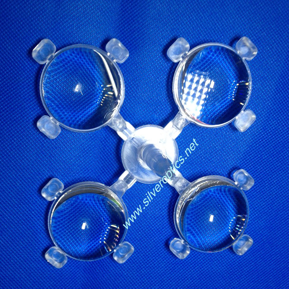
Image: Clear optical component with a rounded body and ribbed extension, shown as a geometry reference.
The rounded body and ribbed extension shown here illustrate why an integrated optical component needs more than an overall shape drawing. Optical surfaces, locating features and handling areas may share one part, but each requires a clear purpose and an appropriate acceptance check.
Separate the functional regions
Mark the useful optical surfaces on the model, then identify the surfaces that locate or support the component. Define which ribs contribute to the optical design and which serve another function. A photograph can show the arrangement, but section views are needed to establish thickness, internal geometry and mating clearances.
Agree where gate remnants, parting lines and ejector contact may be permitted. Keep these proposed locations visible during the design review so a tooling decision does not inadvertently occupy a critical surface.
Review thickness with the molding route
For a molded-polymer design, changes in section thickness require attention because cooling and shrinkage depend on the geometry. Ask the tooling review to address the transition between the main body and extension, rather than treating each region independently.
Select the resin grade against the optical requirement, operating environment and assembly conditions. Record the supplier’s material-preparation guidance with the trial plan. Processing settings should follow the selected grade and observed trial results; the photograph provides no basis for assigning them.
Check the relationship between surfaces
Inspect the optical region relative to the datums used by the assembly. Measure the extension’s position and orientation after the part has reached the agreed inspection condition. If an optical result changes after mounting, compare free-state and assembled measurements before deciding whether the tool needs correction.
Keep trial samples traceable to the drawing revision, resin and cavity. Record both local surface findings and the functional test result.
Prepare a focused quotation request
Provide a sectioned model, labeled optical areas, mating-part geometry, proposed material, inspection criteria and expected quantities. Our optical mold-making overview provides a starting point for the tooling discussion.
Resource
SEND INQUIRY
Related Products
© Silveroptics 2026. All rights reserved
Powered by Silveroptics
Service
