

- Custom Optical Parts
- Lighting & Illumination
- Medical & Endoscopy
- Optical Applications
- Automotive Optics
- Imaging & Vision
- Optical Capabilities
- Products & Applications
- Resource
- Custom Glass Optics
- Optical Molds
- OPtical Coating
- Optical Molding
- Optical Tooling
- Tooling Videos
- Prism & Filters
- Consumer Electronics
- Industrial Vision
- Aspheric Lenses
- Spherical Lenses
Molded Optics: Different Functions, Different Acceptance Tests
Inquiry- Description
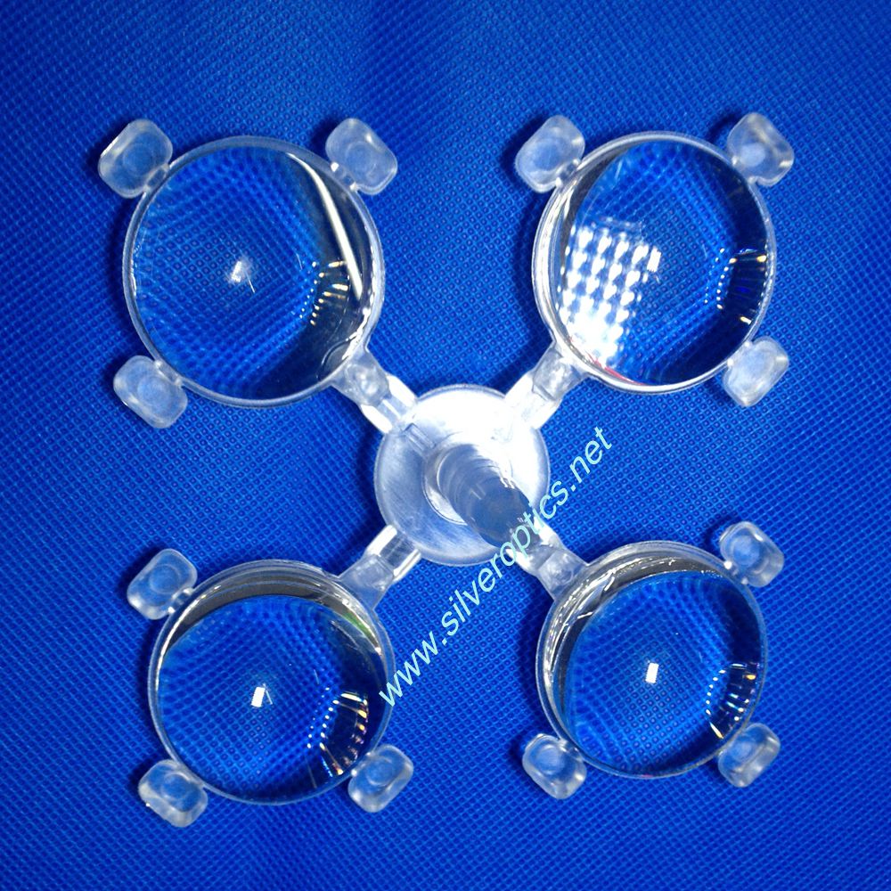
Image: Molded lens parts shown before separation from the runner.
Molded optical parts may all appear transparent, yet their acceptance tests can be very different. The useful starting point is the job the component performs: forming an image, distributing light or carrying light through a measurement path.
Imaging lenses need image-quality evidence
In an imaging system, the lens surfaces and their alignment determine how rays reach the sensor. Surface shape errors or a misplaced element can degrade the image even if the part has no obvious cosmetic defect.
Define the optical prescription, aperture and locating features together. Verify relevant surface and dimensional requirements, then use an agreed imaging test at the specified wavelength, field positions and assembly conditions. A transmission reading alone cannot establish image quality.
Illumination optics need a light-distribution test
LED lenses, arrays and light guides direct light toward an intended area. Their useful result may be a beam pattern or a level of uniformity rather than a focused image.
Check the surfaces that couple and redirect light, along with the features locating the optic to the source. A change in source position or a local molding defect can alter the distribution. Compare trial parts with the same source, fixture and measurement conditions so that differences are meaningful. The automotive optics guide explores these tooling and assembly questions.
Analytical components need a defined optical path
Transparent cells, windows and other analytical components form part of an instrument’s measurement path. Specify the measurement wavelength, path geometry, chemical exposure and cleanliness requirements. Material transmission must be assessed at the relevant grade and thickness.
Stray light, contamination or dimensional variation can affect the measurement. Test the component in a representative instrument or agreed optical setup. Biological-contact and sterilization requirements, where applicable, need their own application-specific assessment.
Build the inspection plan from the function
For each component, connect the required optical result to measurable surfaces, dimensions and assembly conditions. Identify which checks are performed on the insert, the molded part and the final assembly.
Provide the drawing, candidate material grade, service conditions and production volume before tooling review. The optical mold quality guide explains how to distinguish surface, process and finished-part evidence when a trial does not meet its target.
Consumer Electronics, Case Studies
SEND INQUIRY
Related Products
© Silveroptics 2026. All rights reserved
Powered by Silveroptics
Service
