
Fabrication de moules optiques, shaped around your part.
Connect the optical surface, mechanical interface and production plan in one tooling review. Silver Optics supports custom optical molds from the component drawing through mold development and trial evaluation.
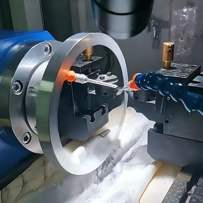
Good optical tooling begins with a complete definition.
A lens drawing needs more than an outer profile. Clear apertures, surfaces optiques, datums and permitted molding marks help turn the intended optical function into a practical mold design.
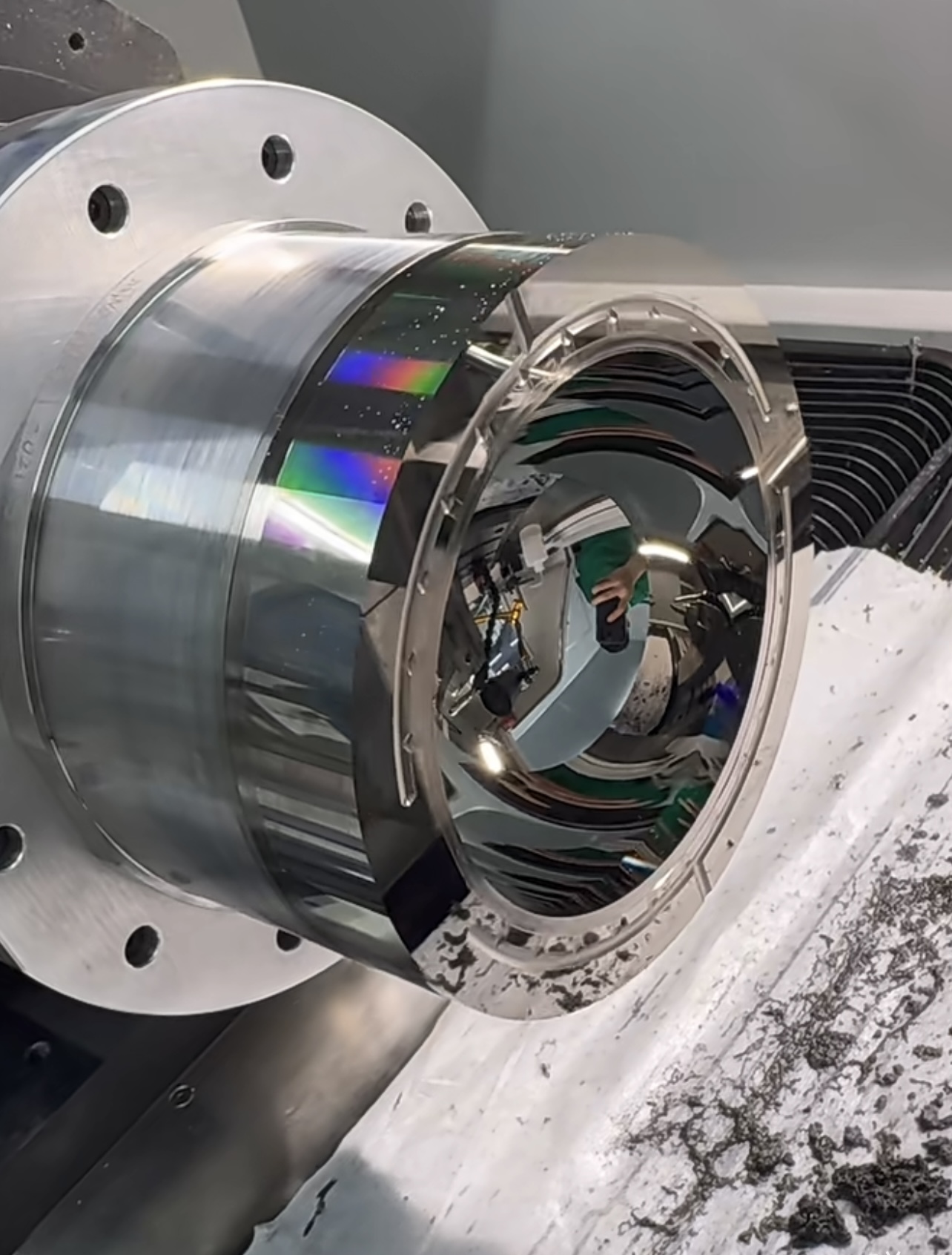
Protect what the light actually uses.
Identify the useful aperture and separate it from mounting rims, gates and handling areas. Relate the optical surface to a stable mechanical reference so mold manufacture and part inspection use the same definition.
- Supply the optical prescription or surface model with the drawing revision.
- Mark surface-form and appearance requirements inside the clear aperture.
- State where parting lines, gate vestiges and ejector contact are restricted.
Balance cavity layout with the production need.
Single-cavity, multi-cavity and family layouts serve different project needs. Cavity count alone does not establish optical quality. Part geometry, material flow, cooling and inspection must be considered together before the layout is fixed.
- Compare quantity and part size with the proposed cavity arrangement.
- Review gate, runner and cooling choices against the functional surfaces.
- Keep replaceable inserts, demolding access and maintenance needs in view.
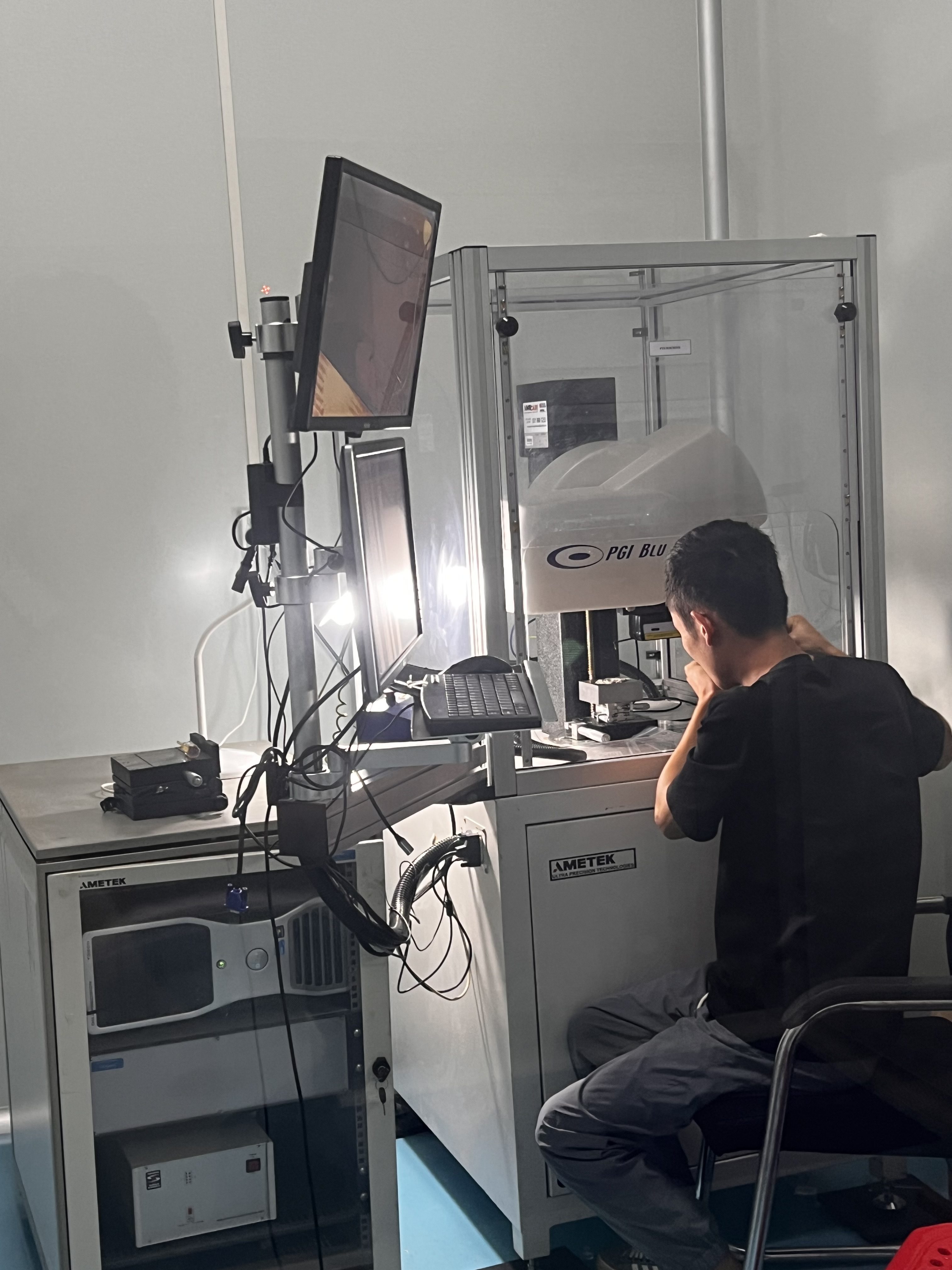
Connect the tool to a measurable trial result.
Mold-surface evaluation and molded-part evaluation answer different questions. Agree how the optical definition, mechanical references and sample results will be compared, so the next step is based on a documented requirement.
- Identify the useful aperture, critical dimensions and reference datums.
- Define the inspection method and the sample evaluation conditions.
- Close tooling or process changes before the approved production stage.
Different optical parts. Different tooling priorities.
Review these geometry types with the optical definition and the proposed molding route. The requirements below are discussion points, not a standard tolerance or guaranteed process.
Lenses & lens families
Ouverture utile, surface geometry and the relationship between each optical element and its mounting features.
Guides lumineux & integrated optics
Optical paths, extraction features and local thickness changes alongside gates, ribs and assembly interfaces.
Patterned optical surfaces
Feature definition, array boundaries and practical replication checks for the intended optical function.
Du premier dessin à l'étape suivante convenue.
- 01
Review the inputs
Align the drawing, optical definition, résine, quantities and intended use.
- 02
Agree the tooling
Confirm cavity layout, critical surfaces, mold interfaces and trial scope.
- 03
Build & evaluate
Review tool manufacture and trial samples against the agreed plan.
- 04
Approve the next stage
Close changes and confirm the accepted revision before production.
Decide acceptance before cutting the tool.
The inspection plan should connect the mold, the molded part and the optical requirement. Methods and limits are agreed for the project.
Mold & insert geometry
Identify datums, critical dimensions and the surface areas requiring form or finish evaluation.
Trial-part checks
Check dimensions, useful-aperture appearance and relevant optical behavior on agreed samples.
Release records
Define revision references, required reports, accepted samples and remaining change actions.
Avant que votre
projet ne commence.
Should I choose a single-cavity or multi-cavity mold?
Start with the component, required output and acceptance plan. The layout also depends on filling, le refroidissement, handling and cavity-to-cavity evaluation. A larger cavity count is not automatically the right solution.
Can the gate be moved away from an optical surface?
Mark prohibited areas on the drawing. Gate position affects filling and stress as well as appearance, so the final location needs a moldability review rather than a visual choice alone.
What is needed to begin a tooling review?
Provide the current drawing and 3D model, la définition des surfaces optiques, material or proposed resin, les quantités et les exigences de réception. Include any existing mold or interface constraints.
Bring the optical requirement into the tooling discussion.
Envoyez la spécification actuelle et indiquez les exigences encore à résoudre. Matériaux, Processus, Tolérances et portée de livraison confirmées après examen technique.
- 2D dessin, 3Modèle 3D et révision
- Prescription optique, aperture and critical surfaces
- Resin, operating conditions and mold interfaces
- Sample quantity, production demand and schedule
- Acceptance plan, reporting and delivery scope
