
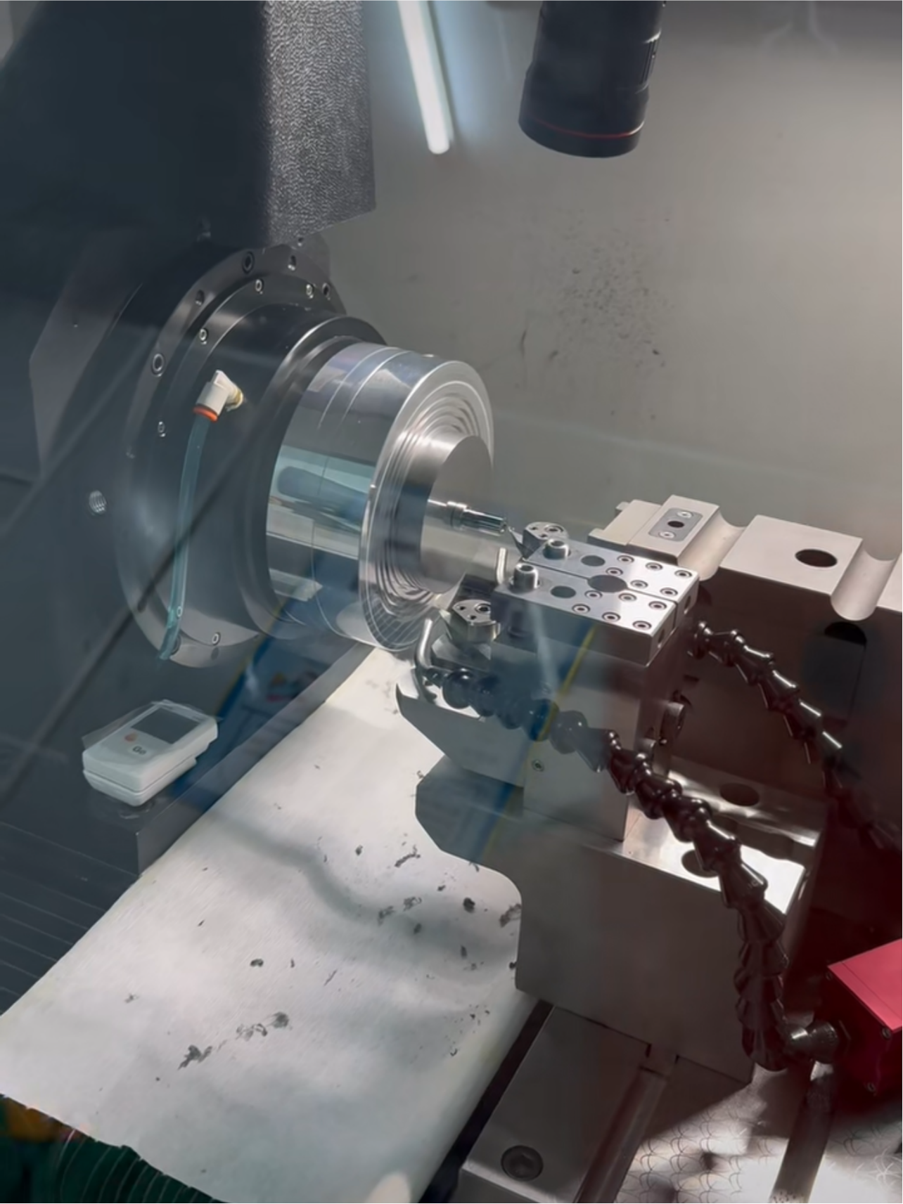
Case Study · Process reference
Diamond-Turned Optical Inserts: Planning Surface Acceptance
A process-led study connects optical geometry, cutting-surface identification, texture reporting and mounting datums in a practical mold-insert review.
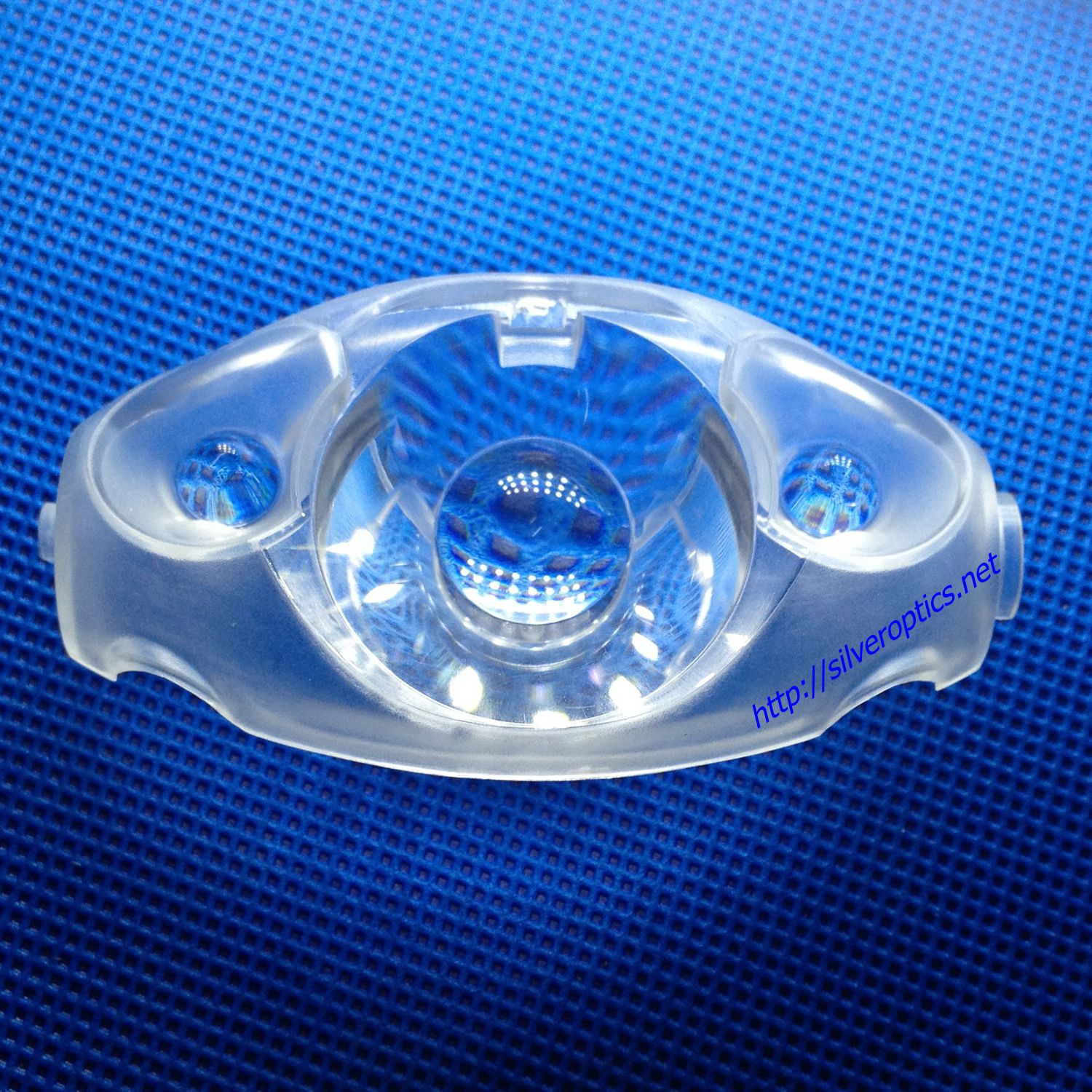
A curved transparent component asks more of a tooling review than a simple outline comparison. Its useful geometry includes the surface shape, the surrounding edge and the features that locate it in an assembly. The Silver Optics presentation brings these questions together through photographs of a circular curved PMMA sample, a mold cavity and the complete mold.
Based on the company presentation’s mold and sample photographs; the review and inspection sequence below is an engineering recommendation, not a record of measured improvement.
The sample photograph shows the overall component form. The cavity view brings attention to the surface-producing region. The full mold photograph provides the wider tooling context. Together, these views make a useful portfolio study, while the optical prescription and exact sample-to-tool traceability remain unspecified.
The visible curvature should be described simply as curved. A photograph alone does not establish an aspheric prescription, a total-internal-reflection function or a particular focal property. Those definitions belong in the optical design data.
Start by marking the working aperture and identifying the surface used to locate the component. Then specify the nominal geometry of the curved region and its relationship to the mounting features. This gives the toolmaker and inspector a common reference for discussing the part.
Separate requirements for surface form, local finish and visible imperfections. They describe different aspects of the surface and should have their own measurement or visual evaluation instructions. As technical context, Taylor Hobson’s optical metrology information treats form and surface finish as distinct measurement tasks for plastic lenses and other optical components.
Avoid assigning a numerical finish or form tolerance from the appearance of the source photograph. Any numerical limit should follow the application, drawing and agreed inspection method.
Use the model to identify proposed gate contact, parting-line location, ejection contact and handling surfaces. Review these against the working aperture and mounting references, and draw the protected regions explicitly.
The same review should consider measurement access. Determine how the component will be supported without obstructing the region being inspected, and how orientation will be reproduced between measurements. Check whether the chosen method can cover the required curvature and aperture before committing to a reporting format.
For the tool, identify which surfaces will be inspected after manufacture and after any finishing operation. Record the approved geometry revision and the areas that require renewed verification if tool work is performed later. The photographs do not establish which machining or finishing route was used.
A proposed evaluation can proceed from the component’s reference geometry toward its optical function:
Keeping these records separate helps reviewers distinguish an assembly-reference issue, a surface observation and an optical-test result.
An effective RFQ includes the curved-surface model or prescription, aperture boundary, mounting datums, material grade and permitted contact regions. Add the inspection method or functional requirement that determines which areas matter most.
Explore оптическим формованием and Silver Optics’ quality information, или send the component definition for discussion.
A process-led study connects optical geometry, cutting-surface identification, texture reporting and mounting datums in a practical mold-insert review.
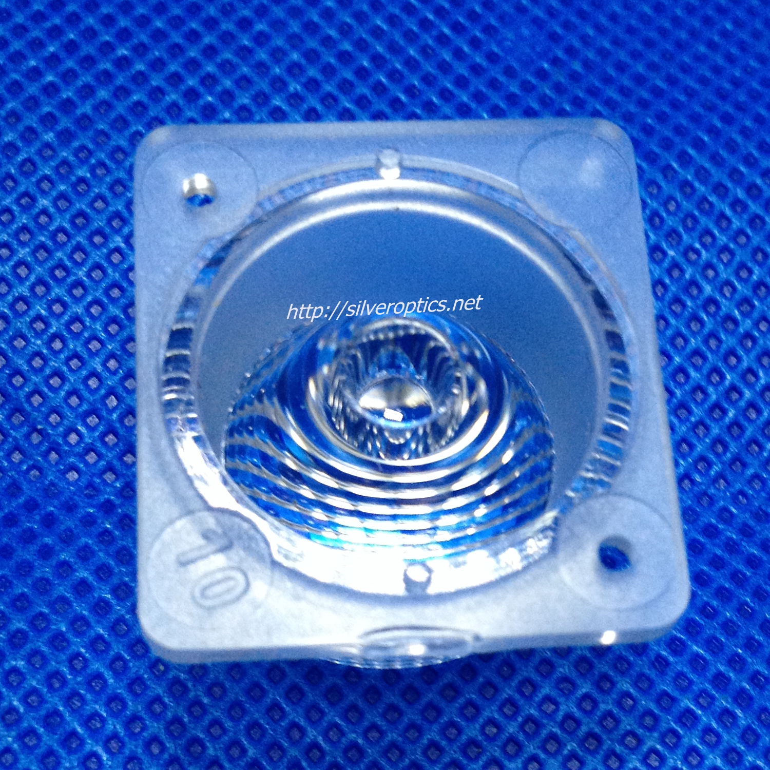
Concentric-ring PC samples and a mold photograph provide the basis for an inspection strategy that records radial position, direction and feature definition.
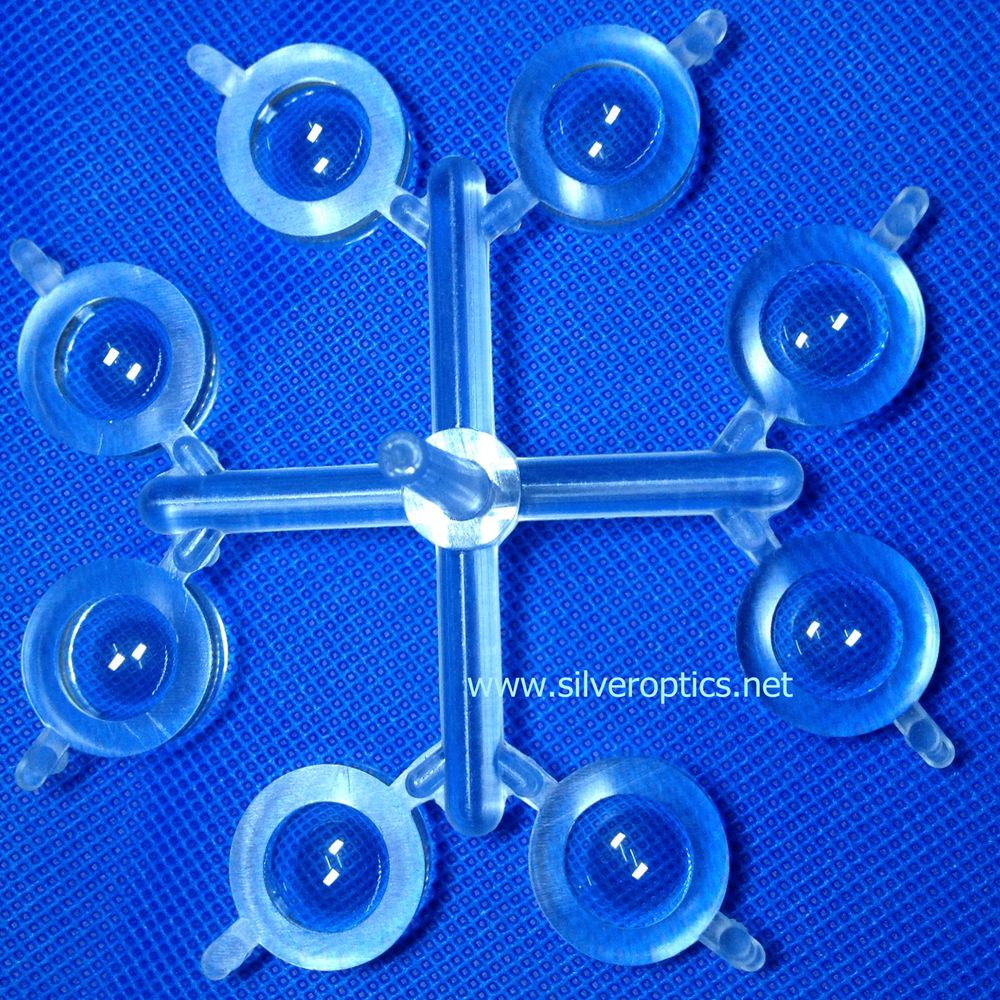
A three-cavity PC portfolio layout provides a concrete basis for preserving cavity identity, comparing complete shots and inspecting samples before and after separation.
Share your optical drawings, material requirements and inspection priorities. Discuss tooling, molding and the next steps with Silver Optics.
