
- Prisme & Filtres
- Pièces optiques personnalisées
- Éclairage & Illumination
- Médical & Endoscopie
- Applications optiques
- Optiques automobiles
- Imagerie & Vision
- Capacités optiques
- Produits & Applications
- Ressources
- Optiques en verre sur mesure
- Moules optiques
- Revêtement optique
- Moulage Optique
- Outillage optique
- Vidéos d'outillage
- Électronique grand public
- Vision industrielle
- Lentilles Asphériques
- Lentilles Sphériques
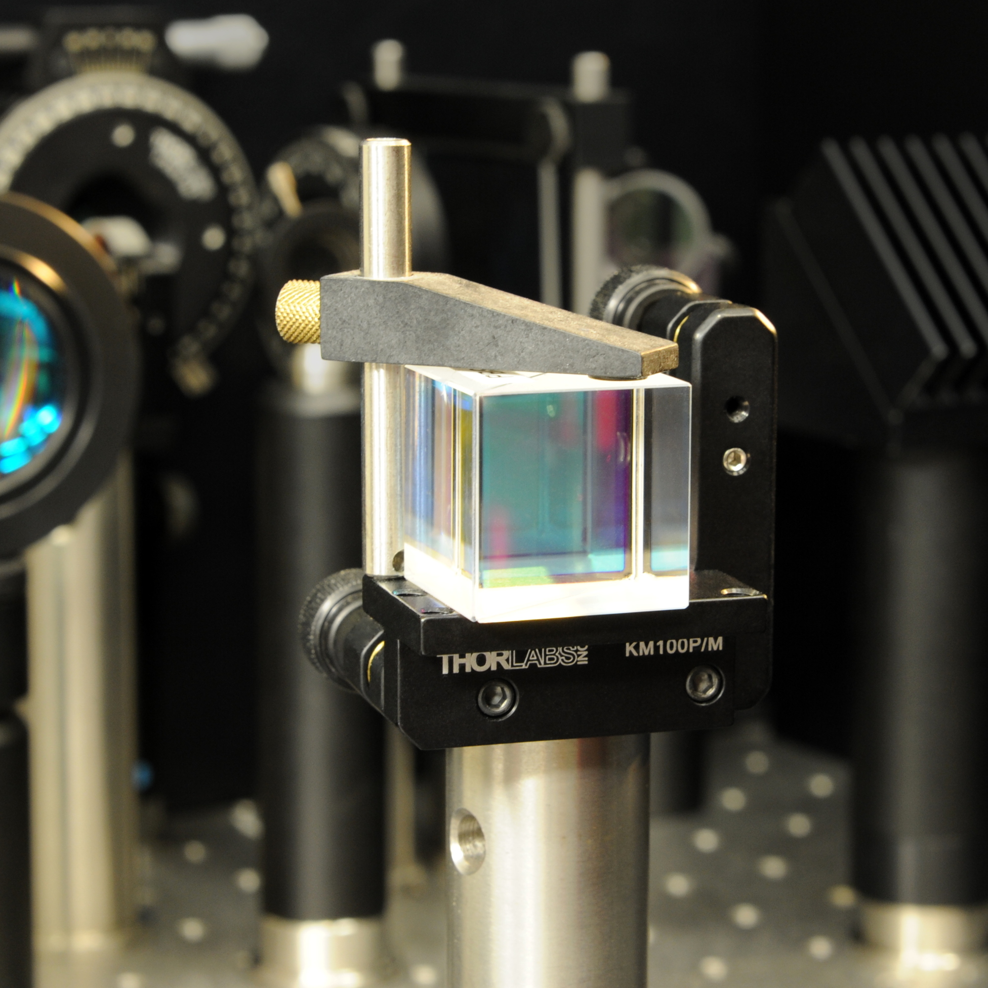
Cube séparateur de faisceau polarisant RFQ: Spécifier les deux ports
Enquête- Description
A polarizing cube beamsplitter can send two orthogonal polarization components to different ports. Both outputs may be used, but they should not inherit the same extinction requirement by default. A transmitted beam that meets its leakage limit does not prove that the reflected channel is clean enough for a second detector. Put the two ports on the drawing and give each its own acceptance conditions.
Write Separate Throughput and Leakage Requirements
For a design intended to transmit p-polarized light and reflect s-polarized light, denote the transmission fractions as Tp and Ts and the reflection fractions as Rs and Rp. Define the transmitted extinction ratio as Tp/Ts and the reflected ratio as Rs/Rp if those are the conventions you intend. La Edmund Optics beamsplitter guide explains why these ratios are generally different.
Also give the minimum desired throughput at each used port. A high ratio by itself is not proof of enough optical power: both the wanted and unwanted components could be low. If one port is unused, state whether it needs a beam dump or a stray-light limit rather than imposing an unnecessary extinction requirement.
Define the Test Geometry and Port Orientation
Identify input, transmitted and reflected faces in a common view. Define how the planes used to label s and p relate to the optical layout. State the wavelength or band, external angle of incidence, any allowed angular spread, and the beam position and diameter at the entrance face. If the cube is installed in a converging beam, give the angular range expected in the instrument rather than asking the inspector to infer it from the cube drawing.
Show the seating face, the permissible orientation-mark location, and any functional clear aperture. Define output beam deviation or spot position only where it drives alignment, and name the reference and measurement geometry. For systems where extra light can reach the detector, la plate-beamsplitter ghost-path guide shows how to document a detector exclusion zone. Its plate geometry is different; use the method to sketch the paths for the actual cube.
Ask for a Report That Separates the Two Outputs
- Transmitted port: wanted throughput, leakage or extinction limit, and wavelength and angle range.
- Reflected port: separate wanted throughput and leakage or extinction requirements, or an explicit unused-port disposition.
- Optomechanical fit: entrance and output faces, mounting orientation, clear aperture and any required beam deviation limit.
- Inspection: agreed input polarization, normalization, detector configuration, usable leakage measurement floor, and sampling.
If measured leakage is near the test setup’s floor, ask for the reporting threshold instead of a more precise ratio than the method supports. For a custom optical component inquiry, summarize the port and acceptance requirements through the Silver Optics inquiry page and arrange transfer of the port sketch separately.
Ressources, Blogs
ENVOYER UNE DEMANDE
Produits connexes
© Silveroptics 2026. Tous droits réservés
Propulsé par Silveroptics
Service
