
- Moulage Optique
- Outillage optique
- Vidéos d'outillage
- Prisme & Filtres
- Pièces optiques personnalisées
- Éclairage & Illumination
- Médical & Endoscopie
- Applications optiques
- Optiques automobiles
- Imagerie & Vision
- Capacités optiques
- Produits & Applications
- Ressources
- Optiques en verre sur mesure
- Moules optiques
- Revêtement optique
- Électronique grand public
- Vision industrielle
- Lentilles Asphériques
- Lentilles Sphériques
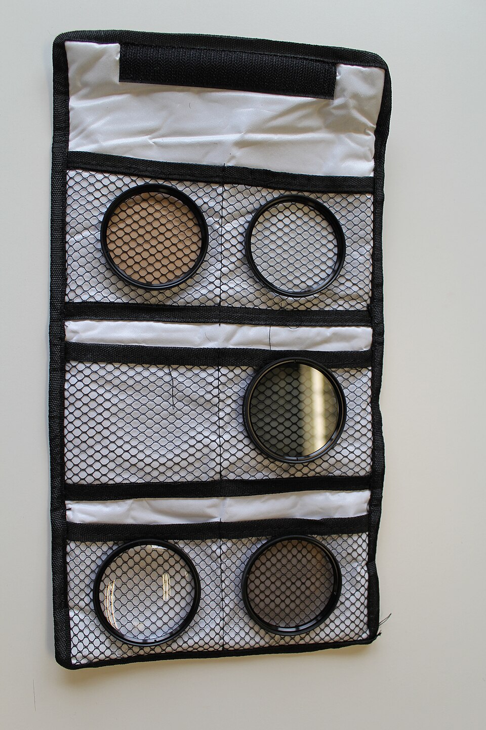
Filtre à densité neutre RFQ: Spécifier la transmission sur toute la bande
Enquête- Description
Choosing a neutral density filter starts with the amount of light the detector can accept. A nominal optical density (OD) alone does not tell the supplier how closely transmission must stay within limits across your instrument’s wavelengths. It also does not say what should happen to the light that does not reach the detector. Give suppliers both requirements so their quotes can be compared.
Translate the OD Target Into an Acceptance Limit
Optical density is the negative base-10 logarithm of the transmitted fraction. Par exemple, OD 2 corresponds to 1% transmission. La Edmund Optics guide to neutral density filters explains the conversion and the distinction between absorptive and reflective designs. Use the conversion to check that the OD on the drawing and the transmission limit in the inspection plan agree.
State whether the target is at one wavelength, an average across a band, or a limit that every measured wavelength in the band must meet. A band average can hide a local peak or dip that matters to a narrowband source or a detector with uneven response. If every wavelength must pass, agree on the measurement interval and spectral bandwidth used to assess it.
Decide Which Unwanted Light Matters
If reflected light can return to a source or reach another detector, draw the relevant optical path and specify the permissible reflection or stray-light level at the point that matters. A reflective filter and an absorptive filter may deliver the same nominal OD while behaving differently in the assembly. Absorption can heat the optic; reflection can create an unwanted beam. Give the supplier the incident power or irradiance and operating conditions if heating or reflected power affects the design.
Specify angle of incidence, polarization where material to the result, and the required clear aperture. If the filter will be used in a converging beam, give the angular range rather than only the chief-ray angle. La coating RFQ guide explains how to document the working angle and polarization separately from mechanical fit.
Request Evidence You Can Compare Across Quotes
- Spectral target: OD or transmission limits, wavelength band, and whether the limit applies point by point or to an average.
- Measurement: angle d'incidence, polarization if specified, beam diameter, wavelength sampling, and the instrument’s useful measurement range at the lowest transmission.
- Mechanical drawing: ouverture claire, outside dimensions, épaisseur, usable area and permissible marks or coating exclusions.
- Release evidence: spectral trace with the sample or lot identifier, agreed sampling frequency, and any separate limits on reflection or spatial uniformity.
For high OD, ask how the supplier distinguishes the transmitted signal from the instrument’s stray-light background. A trace near that floor may be adequate to show a lower bound on OD but not to quantify the true transmission. Agree on the reporting format before deciding how the part will be released.
For a custom optical component review, summarize the spectral target through the Silver Optics inquiry page. Arrange drawing transfer with the team, and flag any limits still awaiting engineering approval rather than asking suppliers to treat them as fixed.
Ressources, Blogs
ENVOYER UNE DEMANDE
Produits connexes
© Silveroptics 2026. Tous droits réservés
Propulsé par Silveroptics
Service
