
Concave and convex inserts
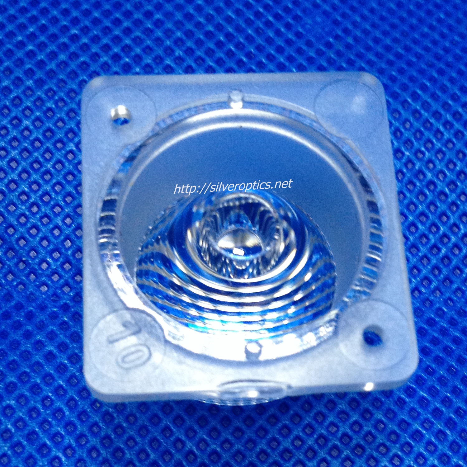
Individual mold surfaces defined by the approved aspheric profile, optical aperture, and surrounding mechanical features.
Carry the approved aspheric design into a clearly specified mold insert. Connect the surface equation, usable aperture, mechanical references, and acceptance method before the manufacturing route is fixed.
 04 / TOOLING
An aspheric surface departs from a spherical profile. For a rotationally symmetric asphere, the changing profile can be described by a sag equation and its coefficients. The insert specification must make that definition unambiguous, including units, orientation, and the surface being described. This provides a common reference for tooling development, measurement, and discussions about the molded optical component.
Individual mold surfaces defined by the approved aspheric profile, optical aperture, and surrounding mechanical features.
Multiple cavities or paired tooling elements with specified relationships and a consistent basis for comparison.
Prototype or replacement tooling that connects a current optical design with its intended mold interface.
A surface definition is most useful when the drawing also explains where it applies and how the insert is located.
Supply the aspheric prescription or an agreed equivalent dataset. Identify the axis, origin, units, and revision so the model and drawing describe the same surface.
Separate the optical zone from lands, chamfers, and mounting features. Identify transitions or steep regions that affect access and require particular inspection attention.
Distinguish the required insert surface from the finished lens prescription. Identify any approved compensation and who controls changes during mold development.
Confirm the equation or nominal dataset, clear aperture, model revision, and relationship to the mechanical drawing.
Select the manufacturing approach around substrate condition, surface depth, local slopes, and nearby features.
Define the stages needed to produce the surface while preserving the optical boundary and specified insert dimensions.
Evaluate the measured profile and accompanying surface checks, documenting any proposed correction against the same reference.
The acceptance package should explain both the measured surface and how it relates to the references used in the mold.
Compare the required aperture with the nominal surface using an agreed alignment and evaluation method.
Define the measurement regions and texture criteria, including any relevant directional or periodic pattern.
Evaluate scratches, pits, the central region, and the transition at the edge of the optical zone.
Check the optical surface against locating dimensions and include matched-cavity comparisons where specified.
It may be part of the specification, but the nominal definition, coordinate convention, and acceptance requirements must also be clear.
No. Material, geometry, and access determine the appropriate route. The aspheric definition describes the surface rather than prescribing one process.
Include the existing mold interface, locating dimensions, current drawing revision, and original inspection criteria, alongside the required optical surface data.
Give Silver Optics the optical and mechanical information together, so the quotation discussion starts from a complete insert definition.
