
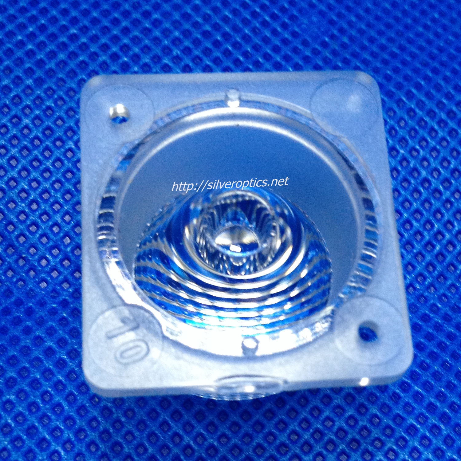
Concentric Fresnel inserts
Circular groove patterns with a defined optical center, clear aperture, and complete radial profile.
Translate the optical design into a complete groove specification. Fresnel tooling brings facet shape, groove spacing, transitions, and optical alignment together on a carefully defined molding surface.
 06 / TOOLING
A Fresnel lens replaces the thickness of a conventional lens profile with a sequence of optical zones. The individual facets redirect light, allowing a thinner optical element. Its mold insert must therefore represent the intended groove geometry as well as the overall pattern. Focal length and outside dimensions alone do not define the machining requirement.
Circular groove patterns with a defined optical center, clear aperture, and complete radial profile.
Fresnel structures with specified pattern direction, segment boundaries, and placement within the insert.
Prototype or replacement tooling based on an approved optical layout and identified replication requirements.
Good Fresnel documentation connects the detail of each groove with the orientation and position of the optical surface.
Provide the nominal facet geometry, pitch or zone positions, and depth definition. Identify where the profile changes across the aperture rather than assuming every groove repeats.
Define permissible radii, step geometry, and non-optical transition faces. These details influence the physical feature that can be produced and reproduced in the molded part.
Show the intended lens orientation and distinguish its surface from the inverse molding geometry. Locate the pattern relative to the optical axis and mechanical references.
Reconcile the groove dataset, nominal lens surface, insert drawing, and any approved tooling compensation.
Assess substrate condition, smallest radii, facet slopes, surrounding geometry, and the selected manufacturing approach.
Plan the pattern sequence and any finishing around the defined facets, center region, peaks, and transition faces.
Verify individual groove details alongside pattern location and overall form, using the agreed sampling and reference system.
The acceptance plan should identify which facets and pattern regions are measured, and how those results relate to the drawing.
Check the specified facet profile, depth, pitch, and allowable transition radii.
Verify optical center or pattern origin, orientation, and location relative to the mold datums.
Evaluate texture and defects on the functional faces using a suitable measurement approach.
Review peaks, roots, segment joins, and selected regions across the usable aperture.
No. The groove geometry also depends on the optical design, material, orientation, and operating arrangement. Supply the approved surface data.
Any finishing must preserve the specified facets and transitions. A general polishing instruction is insufficient for a structured optical surface.
A sample is useful context, but it does not replace an approved nominal definition or clarify every molding allowance and acceptance requirement.
Share the optical definition and insert requirements with Silver Optics to make the initial tooling discussion specific and productive.
