
- Medical & Endoscopy
- Optical Applications
- Automotive Optics
- Imaging & Vision
- Optical Capabilities
- Products & Applications
- Resource
- Custom Glass Optics
- Optical Molds
- OPtical Coating
- Optical Molding
- Optical Tooling
- Tooling Videos
- Prism & Filters
- Custom Optical Parts
- Lighting & Illumination
- Consumer Electronics
- Industrial Vision
- Aspheric Lenses
- Spherical Lenses
Lighting & Illumination
Optical Applications / Lighting & Illumination
Give light a precise direction
Lighting optics turn a source into a defined distribution. A useful project brief connects the emitter, optical surfaces and mounting arrangement with the light the application needs. Start with the beam pattern or illuminated region, then set the conditions that will make sample evaluation meaningful.
Discuss your project >Explore the application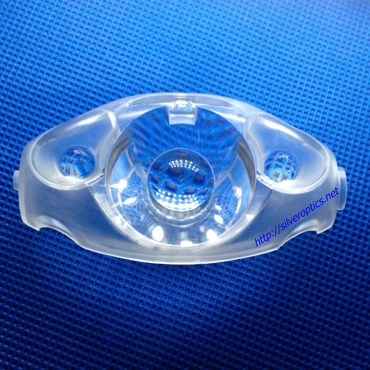
01Beam shaping02Light-guide uniformity03Source & array alignment
Beam shaping
Begin with the source and the target
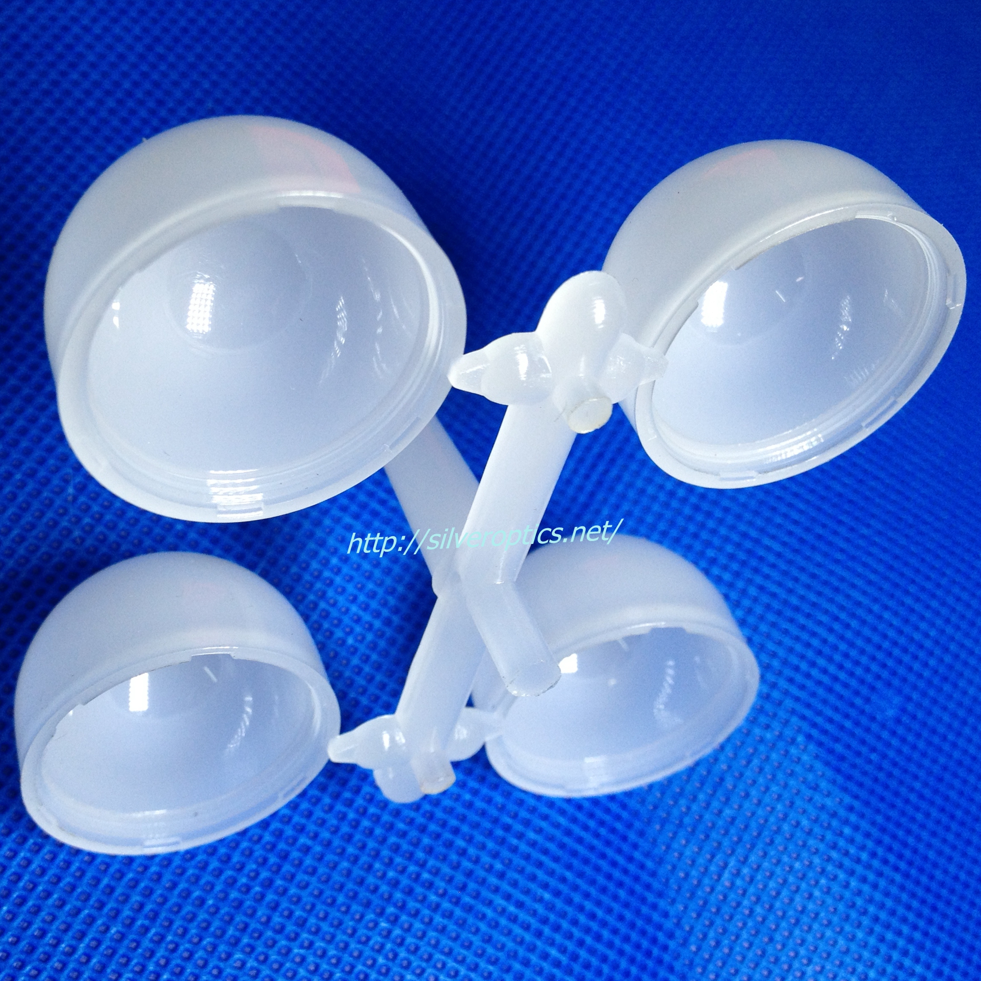
An illumination lens should be reviewed with the source it is intended to control. Provide emitter dimensions, emission data and source-to-optic spacing, then define the target plane or angular distribution. Include the mounting features that maintain this relationship in the finished assembly. Beam width, output distribution and acceptable stray light need agreed measurement conditions so the desired result can guide the component and tooling review. Review the operating temperature and material data alongside the source so the optical assumptions match the proposed installation.
- Source emission data, emitting area and optical spacing
- Target plane, angular distribution and measurement distance
- Beam profile, stray-light limits and mounting datums
Light guides
Define how the illuminated surface should look
For a light guide, specify where light enters, how it travels and where it should emerge. Mark the visible region and any areas excluded from evaluation. An appearance requirement needs defined viewing directions and luminance measurements; lighting a separate surface calls for a specified target and illuminance assessment. Include source drive, housing and alignment in the test setup so sample comparisons stay consistent. For a molded guide, include surface-detail inspection at agreed positions and identify permitted gate and handling locations.
- Input surfaces, source position and visible output region
- Viewing geometry or target-plane measurement grid
- Source drive, housing configuration and uniformity criteria
Optical arrays
Align every element in the array
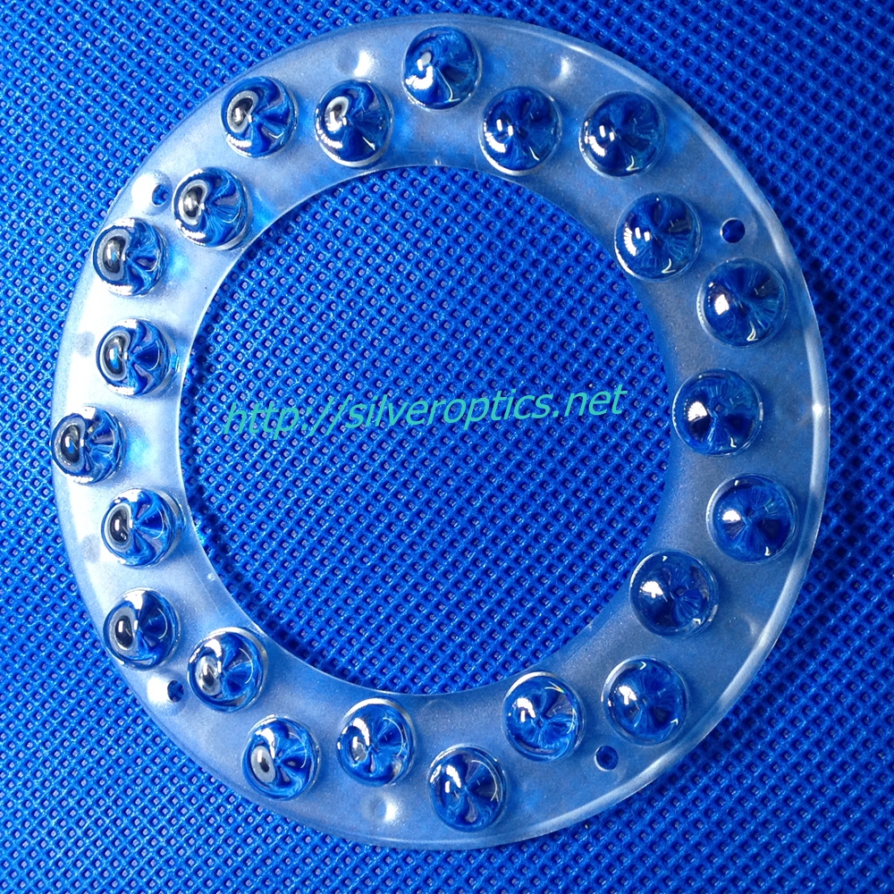
Repeated optical features need a common reference with the emitter layout. Define each element’s position and orientation together with the array center, seating plane and rotational reference. Review the whole component for molding and assembly rather than assessing one repeated feature in isolation. Where practical, examine individual source positions before measuring the combined output so local alignment issues can be distinguished from the overall distribution. Agree trial-part checks for dimensions, surface condition and light distribution before the component moves to the proposed production scope.
- Emitter layout and optical element coordinates
- Common seating plane, center and angular orientation
- Individual-position checks and combined-output acceptance
Project preparation
Bring these details to the project review
Define the light result and the conditions used to measure it. Keep source, material, housing and fixture information consistent through tooling review and trial evaluation.
- Optical model and source emission data with operating conditions
- Required beam pattern, illuminated region or output profile
- Source spacing, housing geometry and alignment references
- Material, temperature exposure and surface requirements
- Measurement setup, acceptance criteria, quantities and schedule
- Molding restrictions, detailed surface features and trial-part inspection requirements
Start a technical conversation
Start with the light you need
Send SILVER OPTICS the source data, component geometry and target distribution. These inputs connect optical design, tooling and sample evaluation in one project discussion.
Discuss lighting optics >© Silveroptics 2026. All rights reserved
Powered by Silveroptics
Service
