
Linear and prismatic structures
Grooves, ribs, and directional facets with specified cross-sections, spacing, and orientation.
Define the smallest functional feature and the pattern it belongs to. Microstructured optical tooling combines local geometry, repeat spacing, feature orientation, and clear boundaries within a complete molding surface.
 07 / TOOLING
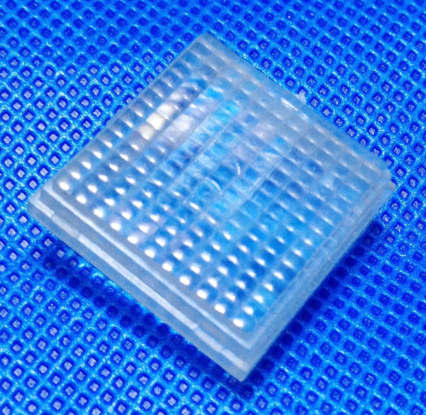
Microstructured optical surfaces use small geometric elements arranged to perform a defined function. Their tooling specification must describe both the individual element and its distribution across the insert. A complete definition includes the nominal shape, spacing, orientation, and relationship to adjacent zones. Manufacturing and inspection planning should begin at that feature scale, then extend to the full pattern and mold interface.
Grooves, ribs, and directional facets with specified cross-sections, spacing, and orientation.
Lenslet, cavity, or other repeated-feature patterns defined by a nominal element and its arrangement.
Multiple feature types or orientations combined within one surface, with explicitly defined boundaries between zones.
Mark the functional dimensions and pattern rules clearly so a local detail cannot be separated from its intended position.
Define width, depth or height, radius, angle, and any required draft. A tool must have practical access to the complete feature without interfering with adjacent geometry.
Specify repeat spacing, orientation, origin, and any deliberate variation. Identify whether acceptance applies to individual elements, selected areas, or comparison between matched cavities.
State which regions require surface refinement and which details must remain untouched. Narrow peaks, junctions, and small radii should have explicit shape requirements after the complete process.
Reconcile detailed sections, nominal feature data, array layout, zone boundaries, and the approved drawing revision.
Connect the pattern origin and orientation to mounting datums, material condition, and the prepared tooling surface.
Plan a suitable manufacturing approach around feature accessibility, material behavior, pattern extent, and protected neighboring areas.
Evaluate the nominated features and locations, then compare the array and zone relationships against the same acceptance rules.
Choose inspection methods and sampling that can resolve the required feature. A view of the complete insert cannot establish every local dimension.
Check the required width, height or depth, angles, and radii against the nominal geometry.
Evaluate pitch, pattern direction, and position relative to the defined origin and mold datums.
Review boundaries for unwanted rounding, burrs, interrupted features, or changes at zone junctions.
Assess required texture and compare selected locations or cavities under consistent reporting conditions.
Material, depth, shape, tool access, neighboring geometry, and the ability to inspect it all influence the manufacturing decision.
No. Include the element shape, height or depth, orientation, array origin, extent, and any intentional variation.
Only when the finishing approach preserves the required geometry. The specification should identify protected features and permitted changes before any finishing is planned.
Provide Silver Optics with enlarged feature definitions alongside the insert drawing to establish a useful manufacturing discussion.
