
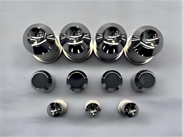
Lens mold inserts
Concave or convex optical profiles with an identified optical axis, clear aperture, and mounting references.
Define the optical surface, its material, and its position in the tool as one engineering requirement. Diamond turning provides a direct route to carefully specified optical geometry on compatible surfaces.
 01 / TOOLING
Single-point diamond turning generates a surface through a controlled cutting motion between the diamond tool and workpiece. Rotational optical forms are a familiar application, while more complex surfaces require an appropriate machine configuration and process. For optical tooling, the essential starting point is a complete definition of the functional surface and the references that locate it within the mold.
Concave or convex optical profiles with an identified optical axis, clear aperture, and mounting references.
Metallic optical masters and development surfaces where both nominal shape and the remaining cutting texture matter.
New or replacement inserts specified against a controlled drawing revision and the surrounding mold interface.
A useful quotation connects material behavior, surface geometry, and an inspection plan before cutting parameters are selected.
Aluminum, copper, and suitable electroless nickel surfaces are established diamond-machining candidates. Steel requires particular care; direct diamond cutting cannot be assumed from the substrate name alone.
Specify the nominal surface, center, aperture, and edge transition. Identify adjacent lands or steps that influence tool access and the available finishing allowance.
Turning can leave a regular surface pattern. Its spacing and direction may be relevant to optical performance, even when an average roughness result meets the drawing.
Bring the model, surface equation or profile data, drawing revision, and mechanical datums into agreement.
Resolve substrate condition, any coating, stock allowance, workholding, and access to the functional surface.
Set the cutting strategy around the approved profile, material response, center region, and aperture boundary.
Compare measured results with the agreed requirements before deciding whether further cutting or finishing is appropriate.
Choose checks that can answer the drawing requirements on the actual geometry. Measurement locations and reporting conventions belong in the project specification.
Does the measured surface agree with the nominal definition throughout the required aperture?
Are roughness, measurement direction, and any periodic cutting pattern evaluated consistently?
Are the center, outer boundary, scratches, burrs, and visible defects acceptable?
Is the optical surface correctly located relative to the seating face and locating features?
No. Material compatibility, geometry, access, and the intended optical function determine whether turning is an appropriate route.
Additional finishing should have a defined purpose. Removing material can also change a carefully generated surface or boundary.
A sample helps explain the requirement, but nominal geometry, datums, and acceptance criteria are still needed for a reproducible specification.
Share the available technical package with Silver Optics to begin a focused tooling discussion.
