
- Medical & Endoscopy
- Optical Applications
- Automotive Optics
- Imaging & Vision
- Optical Capabilities
- Products & Applications
- Resource
- Custom Glass Optics
- Optical Molds
- OPtical Coating
- Optical Molding
- Optical Tooling
- Tooling Videos
- Prism & Filters
- Custom Optical Parts
- Lighting & Illumination
- Consumer Electronics
- Industrial Vision
- Aspheric Lenses
- Spherical Lenses
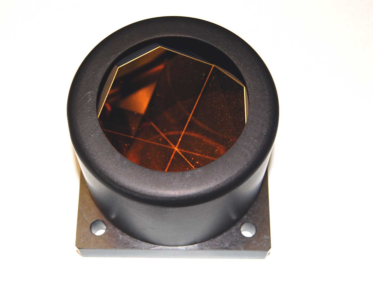
Corner-Cube Retroreflector RFQ: Define the Return Beam
Inquiry- Description
A corner cube sends light back toward the incident direction through three reflections. In an instrument, what matters is whether the receiver gets enough light in the right place over the orientations and beam positions it actually sees. Put return angle, aperture and signal requirements on the same sketch before requesting a quote.
Separate Return Direction From Receiver Capture
Set a limit on return-angle error relative to the intended antiparallel direction. Define the incoming beam diameter and position, receiver location and useful collection aperture. An angular result alone does not guarantee receiver coupling: a laterally shifted or clipped beam can still miss the useful detector area.
Specify whether the receiver requirement is expressed as spot position at a defined plane, collected power, or both. List the operating wavelength or band and the range of incident angles about the mounted orientation. Use optical rather than outside diameter for the useful opening. Edmund Optics’ fused-silica example illustrates the distinction between clear aperture and return beam deviation; its catalog values are not generic acceptance limits.
Specify the Construction and Mechanical References
A solid prism and a first-surface reflector assembly do not use the same optical path. State whether construction is prescribed or open to supplier review. For a solid version, ask which faces use total internal reflection or a reflective coating and whether the proposed arrangement covers the stipulated wavelength and incidence range. Give any environmental or protection requirements instead of selecting a finish from appearance alone.
Mark the input face, mounting datums, permissible rotation and retention zones. If the design uses a tight receiver aperture, ask for results at representative positions across the usable region, not only at the center. The Silver Optics inspection overview explains why datums and measurement conditions are agreed against the approved drawing; for a retroreflector, make each of those references explicit.
Agree on Return Evidence Before Ordering
- Define input location, diameter, angle range and wavelength.
- Set return-angle limits and any collected-signal target under stated test conditions.
- Identify clear aperture, mounting datums and coatings by face where applicable.
- Ask for a sketch of the test and results labeled by specimen and tested orientation.
For a custom optical-component review, summarize the return geometry and acceptance limits through the Silver Optics inquiry page and arrange any drawing exchange separately.
Resource, Blogs
SEND INQUIRY
Related Products
© Silveroptics 2026. All rights reserved
Powered by Silveroptics
Service
