

- OPtical Coating
- Optical Molding
- Optical Tooling
- Tooling Videos
- Prism & Filters
- Custom Optical Parts
- Lighting & Illumination
- Medical & Endoscopy
- Optical Applications
- Automotive Optics
- Imaging & Vision
- Optical Capabilities
- Products & Applications
- Resource
- Custom Glass Optics
- Optical Molds
- Consumer Electronics
- Industrial Vision
- Aspheric Lenses
- Spherical Lenses
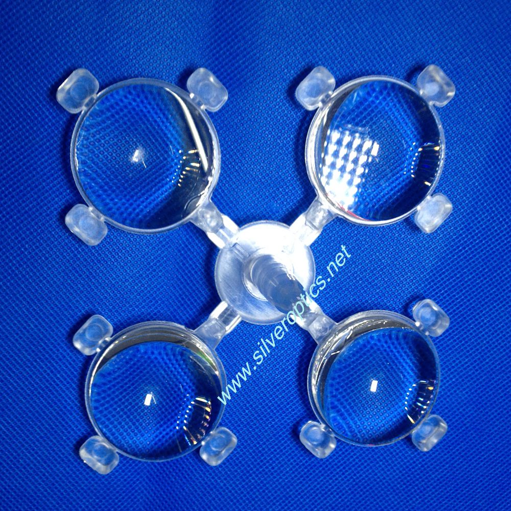
Optical Parts with Tabs: Planning Runner Removal
Distinguish retained tabs from sacrificial features and gate-removal areas. Review support, trimming limits and edge inspection as part of the optical component design.
Inquiry- Description
Image: Four clear round optical parts with small peripheral tabs, still joined to the central runner.
Four round optical parts with peripheral tabs are shown connected to a central runner. Before specifying separation, establish which features belong to the finished component. A visible tab may have a retained function or be sacrificial; the photograph alone cannot determine that.
Mark the finished-part boundary
Use the drawing to identify retained tabs, approved handling areas and the gate-removal zone. Show the final edge profile and the allowable remaining projection at each cut location. Keep those limits distinct from the clear aperture and any surface that seats in an assembly.
This prevents a removal instruction from accidentally deleting a locating feature or leaving material where the housing needs clearance. If a tab is intended for handling, confirm whether it remains through inspection, coating or assembly, and which operation removes it.
Trial the separation method with the chosen resin
Review the proposed material grade and the actual gate section before selecting a cutting method. Define how the component and runner will be supported, where the tool approaches, and how separated pieces will be collected. Keep contact away from the specified optical area wherever the design permits.
Evaluate the support and cut sequence on trial parts. Inspect the area for cracks, whitening, loose particles and unwanted protrusions, using agreed lighting and magnification. Record the observations by location instead of relying on a general statement that the edge looks acceptable.
Link edge acceptance to the next operation
Check the trimmed profile against the mating component or an agreed gauge where clearance is critical. Confirm that retained tabs still meet their dimensional requirements. If separation could affect the optical result, include a controlled comparison in the trial plan and document the fixture used.
For a manufacturing review, send a marked-up drawing showing permanent features, removal boundaries, optical no-contact areas and the next assembly step. Specify whether delivery is required on the runner or as individual parts. This defines the requested supply condition as well as the molded geometry.
Resource
SEND INQUIRY
Related Products
© Silveroptics 2026. All rights reserved
Powered by Silveroptics
Service
