

- Prism & Filters
- Custom Optical Parts
- Lighting & Illumination
- Medical & Endoscopy
- Optical Applications
- Automotive Optics
- Imaging & Vision
- Optical Capabilities
- Products & Applications
- Resource
- Custom Glass Optics
- Optical Molds
- OPtical Coating
- Optical Molding
- Optical Tooling
- Tooling Videos
- Consumer Electronics
- Industrial Vision
- Aspheric Lenses
- Spherical Lenses
Annular Optical Arrays: Aligning the Optic and Light Sources
An annular array needs a shared reference between its repeated optical elements, source layout and mounting features. Plan that alignment and verify individual positions before assessing the combined output.
Inquiry- Description
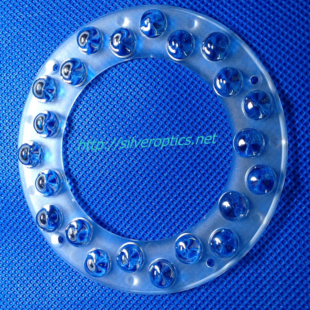
Image: Annular component with repeated curved optical features and smaller holes around a central opening.
The photographed ring combines repeated curved features around a central opening. For a project that pairs this kind of annular optic with multiple light sources, a key design question is how each optical element will remain aligned with its corresponding emitter.
Establish one coordinate system
Place the source layout and optic model in the same assembly reference. Define the ring center, axial seating plane and angular orientation. A circular outline alone leaves rotational positioning unresolved; identify the feature that establishes that orientation in the proposed assembly.
Specify each optical element’s position and orientation rather than relying only on a nominal ring diameter. Include the emitting area’s location and the intended source-to-optic spacing. Confirm the role of any smaller holes shown in the design instead of assuming they are mounting points.
Review the complete ring for molding
If injection molding is selected, review filling, venting and cooling around the full annulus. Ask where flow paths meet and whether those locations intersect specified optical areas. These are tooling-review questions, not defects demonstrated by the photograph.
Compare candidate resin grades against the source spectrum and expected thermal environment. Keep material data and optical-design assumptions consistent through sampling. Supplier specimen values should not become a finished-array transmission guarantee.
Test local alignment and combined output
Begin with dimensional evidence for the seating features and element positions. Then use a representative source assembly to evaluate the optical result. Record the source type, operating condition, spacing and orientation so later samples can be tested on the same basis.
Where individual sources can be operated separately, consider checking each position before measuring the combined output. This proposed diagnostic sequence can help distinguish a local problem from an assembly-wide alignment issue. Define the acceptable measurement variation before using the test for release.
Information for an array RFQ
Send the optic model, source-board layout, mounting stack, required output distribution and agreed test conditions with your quantities through SILVER’s contact page.
Consumer Electronics
SEND INQUIRY
Related Products
© Silveroptics 2026. All rights reserved
Powered by Silveroptics
Service
