

- Products & Applications
- Resource
- Custom Glass Optics
- Optical Molds
- OPtical Coating
- Optical Molding
- Optical Tooling
- Tooling Videos
- Prism & Filters
- Custom Optical Parts
- Lighting & Illumination
- Medical & Endoscopy
- Optical Applications
- Automotive Optics
- Imaging & Vision
- Optical Capabilities
- Consumer Electronics
- Industrial Vision
- Aspheric Lenses
- Spherical Lenses
Linear Light Guides: Defining the Illumination Test
Inquiry- Description
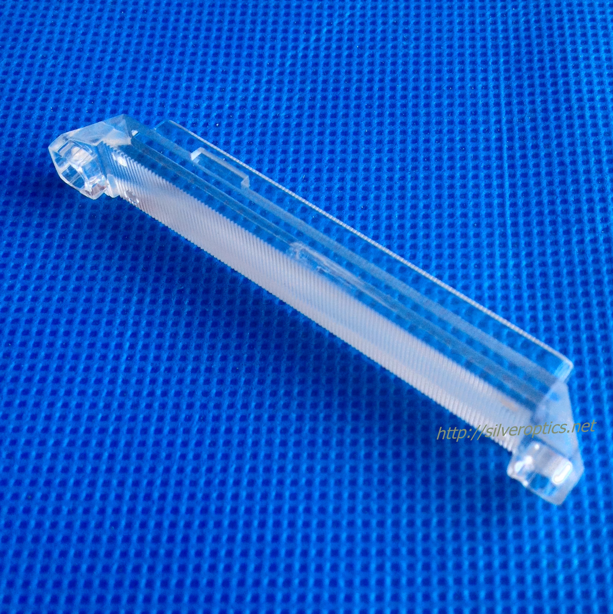
Image: Long clear guide-like component with a finely ridged face and shaped ends, shown as a geometry reference.
A linear light-guide project needs a defined illumination result before the surface pattern can be judged. The long transparent component shown here has a finely ridged face and shaped end features. Its photograph establishes the geometry to discuss, while the optical drawing must define how light enters, travels through and leaves the proposed guide.
Describe the source and visible region
Identify the intended input surface, source position and spacing. State whether the design uses one source or several, and supply their emission data. Mark the length and width over which illumination will be assessed, including any end regions excluded from the requirement.
Define the viewing direction or target plane. For an appearance requirement, agree the luminance measurement positions and viewing geometry; for illumination of a separate surface, define the target and its illuminance measurement grid. Avoid using a photograph taken at an unspecified exposure as the acceptance test.
Develop the material and surface pattern together
Optical guides rely on controlled input and output surfaces. Select a candidate resin using the intended wavelength range and environmental requirements, then assess the proposed geometry with that material’s optical data.
For a molded design, review how the long body and detailed face will be formed, cooled and released. Specify where gate removal, handling contact and any surface marks are allowed. Request inspection of the detailed face at agreed positions along the guide so the ends and middle are represented.
Compare samples in a repeatable assembly
Measure the guide’s fit and alignment in a representative housing before evaluating illumination. Keep source drive, source location, housing configuration and measurement geometry consistent across samples.
Record the output profile along the specified region together with the sample identity. If a local bright or dark area appears, compare its position with surface observations and assembly contacts before choosing a correction.
Start the project review
Provide the model, source data, housing interface, target illumination profile and test method with the expected volumes. See our optical molding overview for the broader production discussion.
Consumer Electronics
SEND INQUIRY
Related Products
© Silveroptics 2026. All rights reserved
Powered by Silveroptics
Service
