


- Products & Applications
- Resource
- Custom Glass Optics
- Optical Molds
- OPtical Coating
- Optical Molding
- Optical Tooling
- Tooling Videos
- Prism & Filters
- Custom Optical Parts
- Lighting & Illumination
- Medical & Endoscopy
- Optical Applications
- Automotive Optics
- Imaging & Vision
- Optical Capabilities
- Consumer Electronics
- Industrial Vision
- Aspheric Lenses
- Spherical Lenses
Flanged Optical Parts: Define the Mounting Reference
Connect the useful optical aperture to the rim that locates the part. Define seating surfaces, mechanical references and inspection conditions before committing to tooling.
Inquiry- Description
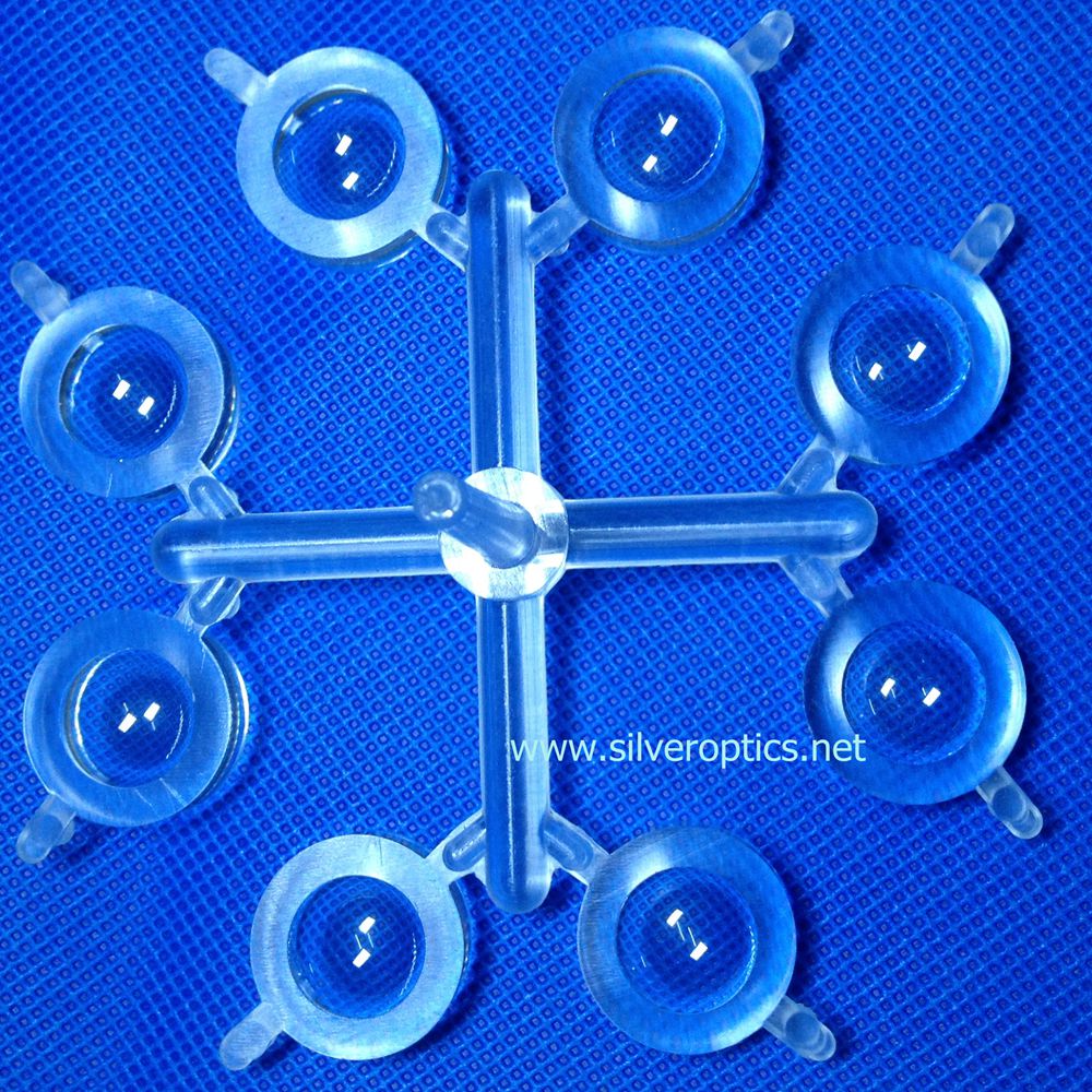
Image: Round optical parts with broad rims, connected to a cross-shaped runner before separation.
The photograph shows eight round optical parts with broad surrounding rims, still connected to a runner. For a flanged optic, the engineering question is how the optical surface will be located and supported in the finished assembly.
Separate aperture, seating and clearance
Identify the clear aperture on the drawing: the region required to meet the optical specification. Then mark which rim surfaces seat against a housing, which feature locates the part laterally, and which areas need assembly clearance. A transparent rim is not automatically part of the specified aperture.
If the design uses an optical axis, define its relationship to the mechanical locating features. An outside diameter check alone cannot verify that relationship. A broad flange can offer space for seating or handling, but those functions need an explicit design decision.
Review the rim and optical region together
For a molded design, review changes in section thickness between the optical region and flange with the proposed resin and process. Cooling and shrinkage are part of the tooling discussion. Confirm the material grade against both the optical requirement and the intended mounting environment.
Show permissible gate and parting-line locations relative to the seating face. Where a trimmed gate could meet the housing, specify the available clearance and an inspection method. Keep the mount drawing available during this review; a component drawing without its mating interface can leave important contact conditions unresolved.
Verify the part in its intended reference system
Inspect the agreed seating and locating features, then assess the optical surface relative to those references. Where assembly loading matters, compare the required optical result in a defined free-state fixture and a representative mount. Record the support points and loading conditions so another inspection can reproduce the setup.
To request a project review, provide the part and mount drawings, clear aperture, optical-axis requirement, material preference and expected assembly method. These details help turn a visually simple round component into a reviewable tooling specification.
Consumer Electronics
SEND INQUIRY
Related Products
© Silveroptics 2026. All rights reserved
Powered by Silveroptics
Service
