


- Optical Applications
- Automotive Optics
- Imaging & Vision
- Optical Capabilities
- Products & Applications
- Resource
- Custom Glass Optics
- Optical Molds
- OPtical Coating
- Optical Molding
- Optical Tooling
- Tooling Videos
- Prism & Filters
- Custom Optical Parts
- Lighting & Illumination
- Medical & Endoscopy
- Consumer Electronics
- Industrial Vision
- Aspheric Lenses
- Spherical Lenses
Round Molded Optics: Specifying Surface Replication
Translate an optical drawing into separate tool-surface and molded-part acceptance checks. Define shape, texture and measurement conditions before selecting a finishing route.
Inquiry- Description
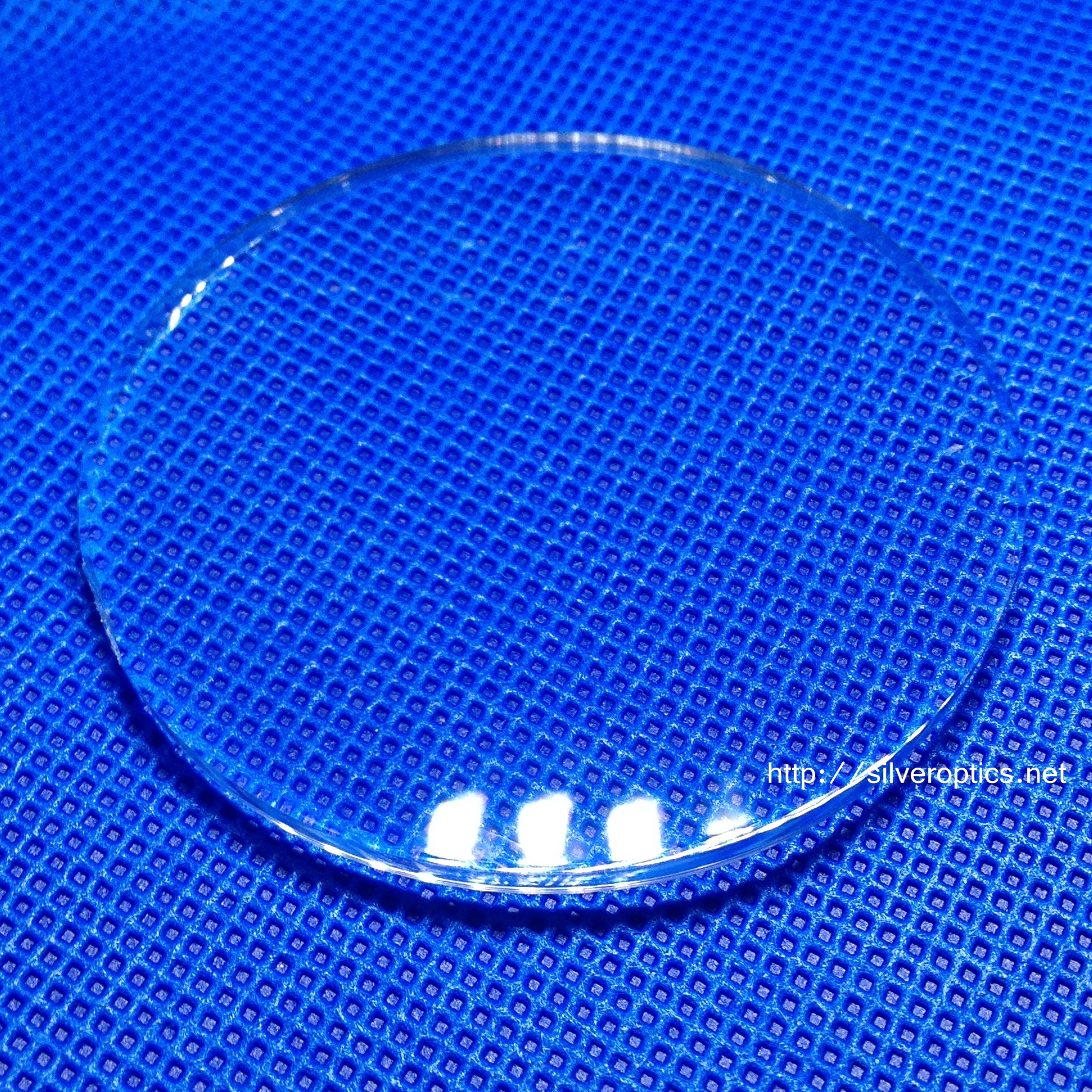
Image: A clear round component on blue fabric. Surface geometry and optical requirements must be established by the project drawing.
A clear round component can look smooth while leaving its optical surface quality unresolved. The photograph provides a geometry reference; it does not establish the surface prescription, roughness or optical performance. For a molding project, those requirements must be connected to measurable tooling and part deliverables.
Describe the surface beyond its appearance
Start with the nominal surface geometry and the area over which it applies. Specify surface-form error, texture and permissible local defects separately. Form describes departure from the intended shape; roughness concerns much finer surface variation. A single description such as “mirror finish” leaves these requirements open.
For texture measurements, agree the sampled region, measurement method and spatial bandwidth. For shape measurements, define how the measured data will be aligned with the nominal surface. These details help prevent two apparently different reports from simply reflecting different analysis settings.
Connect the insert to the molded component
The insert establishes the forming surface, while the finished geometry also depends on the resin and molding process. Review shrinkage and cooling alongside the proposed material grade before finalizing the tool surface. Select a finishing route that suits the specified geometry and tool material, with a corresponding inspection plan.
Define two deliverables for trials: the relevant insert measurement and the molded-part result. Keep their coordinate references and evaluated areas clear. Agreement with the insert requirement is useful evidence, but the component still needs its own acceptance check.
Use trials to resolve the remaining difference
Compare measured parts with the optical drawing under agreed conditioning and fixturing conditions. If the result misses the target, review the insert data, process record and measurement setup together before deciding on a tool correction. Repeat the same evaluation after any agreed change.
For an RFQ, provide the surface model or prescription, optical aperture, material preference and required inspection output. Include any existing measured surface maps. The optical mold-making page outlines the information needed to discuss tooling and trial scope.
Consumer Electronics
SEND INQUIRY
Related Products
© Silveroptics 2026. All rights reserved
Powered by Silveroptics
Service
