

- OPtical Coating
- Optical Molding
- Optical Tooling
- Tooling Videos
- Prism & Filters
- Custom Optical Parts
- Lighting & Illumination
- Medical & Endoscopy
- Optical Applications
- Automotive Optics
- Imaging & Vision
- Optical Capabilities
- Products & Applications
- Resource
- Custom Glass Optics
- Optical Molds
- Consumer Electronics
- Industrial Vision
- Aspheric Lenses
- Spherical Lenses
Circular Multi-Feature Optics: Defining a Common Datum
Inquiry- Description
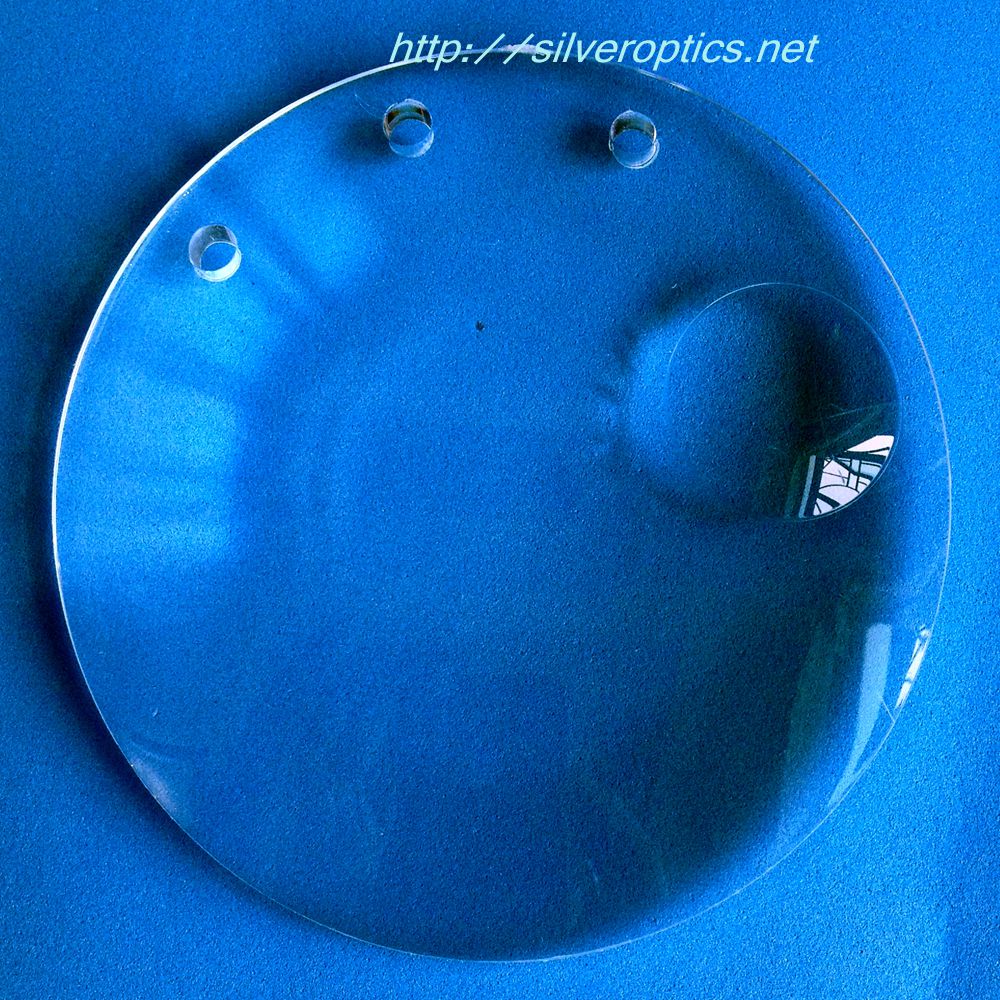
Image: Clear circular component with smaller raised features and a larger curved region, shown as a geometry reference.
When several optical features share one circular component, measuring each feature in isolation can leave their relationship unresolved. The pictured part combines a broad clear circular body, smaller raised features and a larger curved region. A useful engineering specification connects those regions to the same assembly reference.
Give every functional feature an identity
Label the optical zones on the drawing and describe the required function of each. Identify whether the surrounding body also has an optical role. Keep cosmetic areas, optical apertures and mechanical contact surfaces distinguishable so inspection effort follows the actual requirement.
Define the coordinate origin, seating reference and angular orientation. For each functional feature, specify its position and orientation within that system, together with its local surface description. Overall diameter alone cannot communicate an asymmetric arrangement of smaller features.
Review the shared body as one molded part
For a proposed polymer design, compare candidate grades using the complete component’s optical and environmental requirements. Laboratory material data should be treated as selection evidence; the finished design still needs validation.
Ask the tooling review to consider the transitions between the broad body and local raised regions. Document proposed gate, vent and ejection locations on the same feature map. Confirm how the specified surfaces will remain accessible for inspection and protected during removal and packaging.
Combine local and assembly-level evidence
Choose measurement methods for both the local surface geometry and the relative feature positions. Keep the datum alignment consistent when comparing samples. Report any local best-fit result separately from datum-based positional checks. This keeps local-shape results distinct from assembly-alignment evidence.
Where the design has multiple optical functions, give each an acceptance test and also check the complete component in its representative mounting condition. Record failures by feature identity so a local result does not disappear within one overall average.
Send a feature-based RFQ
Provide a labeled model, datum drawing, mating geometry, material constraints, feature-specific requirements and expected quantities. The optical mold-making overview can help frame the discussion around the complete component.
Consumer Electronics
SEND INQUIRY
Related Products
© Silveroptics 2026. All rights reserved
Powered by Silveroptics
Service
